HV Breakout Modules
Measurement of internal conductor current and voltage as well as power measurement directly in HV cables
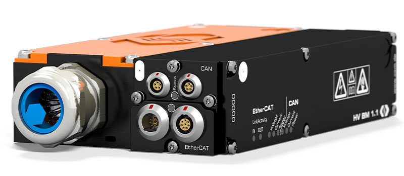
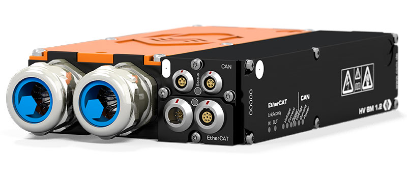
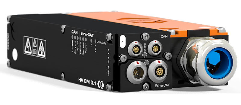
The HV Breakout Modules (BM) are specifically designed for safely measuring directly from HV voltage power cables. Currents and voltages are measured directly and the raw data is acquired at up to 1 MHz per channel. With the Vector eMobilityAnalyzer software, which is optimally paired to the CSM HV Breakout Modules, real time power analysis is also possible.
- Measurement of voltage (U) and current (I) in HV applications
- Nominal voltages up to ±1,000 V (measurement range up to ±2,000 V)
- Currents up to ±1,000 A (nominal), ±2,000 A (peak)
- Simultaneous EtherCAT® and CAN bus communication
- Output of voltage, current and instantaneous power with up to 1 MHz measurement data rate each
- Optional calculation of power and RMS values directly in the module and output via CAN
- In-depth online power analysis with the Vector eMobilityAnalyzer
Overview HV Breakout Modules
The HV Breakout Modules are an important component of the Vector CSM E-Mobility Measurement System and provide the basis for a wide range of measurement applications in vehicle electrification. Current and voltage are measured synchronously - a basic requirement for precise power calculations.
The sensors and measurement electronics of the HV Breakout Modules are well shielded in a very confined, safe space and housed together in a compact enclosure. This simplifies the instrumentation by eliminating the need for sensor cables between the sensors and the measurement device, which could be exposed to interference and thus falsify the measurement signal.
With the various connection options, the HV Breakout Modules can be easily installed into the HV power cables on test benches and in test vehicles.
The HV Breakout Modules feature an integrated shielding concept - avoiding tedious additional work for handling the cable shield.
The robust design with an IP 67 rating and an operating temperature range -40 °C to +120 °C also allows on-vehicle installation for road tests. In this way, the same measurement system can be used to acquire data on the test bench and validate it in the road test.
With the Option Calculated Channels, active, apparent and reactive power, power factor as well as the RMS values for current and voltage are calculated directly in the module from the sampled measured values. Via CAN, the calculated values are directly transferred to the measuring computer or a data logger. This allows analyses to be carried out without the use of special hardware and software. More in-depth analyses are performed with the Vector CSM E-Mobility Measurement System.
Overview
Module overview
| Designation | Phases | Measurement of | Cable connection | Data output | |||
|---|---|---|---|---|---|---|---|
| Inner conductor current | Voltage | Instantaneous power | Power and RMS values | ||||
| HV BM 1.1 | 1 | X | X | X | X | 1 ring terminal per side |
EtherCAT® and CAN simultaneous |
| HV BM 1.2 | 1 | X | X | X | X | 2 ring terminals per side |
EtherCAT® and CAN simultaneous |
| HV BM 3.1 | 3 | X | X | X | Phoenix terminals | EtherCAT® and CAN simultaneous |
|
Click on the corresponding module designation for more information.
Technical overview
| Designation | Phases | Max. measurement ranges | Max. measurement data rates | |||
|---|---|---|---|---|---|---|
| Rated current | Nominal voltage | XCP-on-Ethernet | ECAT | CAN | ||
| HV BM 1.1 | 1 | ±125 A 1) | ±2,000 V 2) | - | 1,000 kHz | 10 kHz |
| HV BM 1.2 | 1 | ±1,000 A 1) | ±2,000 V 2) | - | 1,000 kHz | 10 kHz |
| HV BM 3.1 | 3 | ±32 A | ±1,000 V | - | 500 kHz | 5 kHz |
1) Maximum size of the shunt inside the modules. Additional shunt options can be found in the data sheet.
2) For the detection of transient overvoltage the measuring range is dimensioned to ±2,000 V.

 Home
Home Newsletter


