Home
Home Newsletter
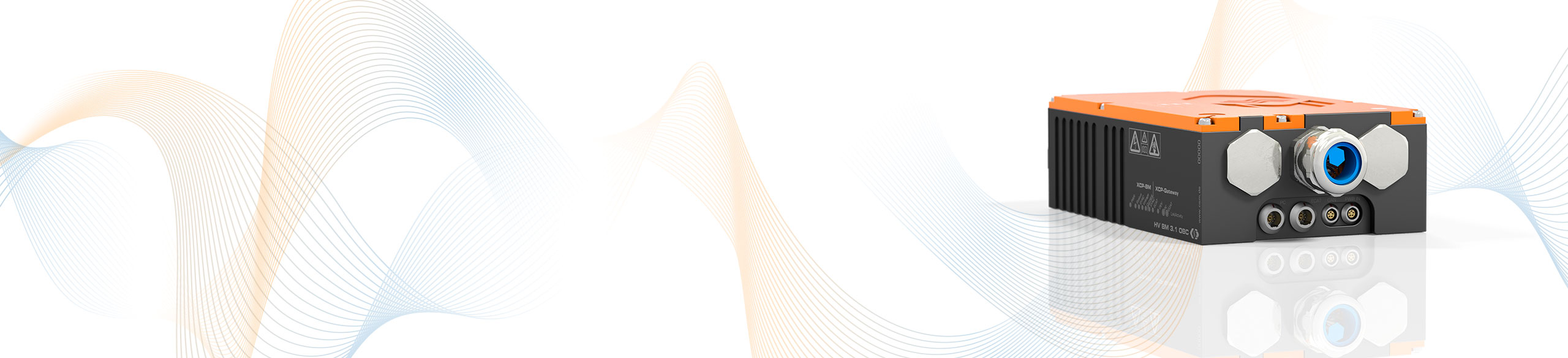
HV Breakout Module 3.1 OBC
Single- to three-phase measurement of current, voltage and power on cables carrying mains voltage for worldwide use
The HV Breakout Module (HV B) 3.1 OBC (on-board-charger) is particularly suitable for measurements during AC charging processes of electric and hybrid vehicles due to its current measurement ranges.
Highlights
- Measurement star voltages U1, U2, U3 measured against N (line-to-neutral, wye configuration) and phase currents (I) I1, I2, I3 in HV applications
- Nominal voltages up to 707 Vrms (measurement range up to ±1.000 V)
- Currents up to ±88 Arms, ±125 A (Peak)
- GBit/s XCP-on-Ethernet interface, measurement data rate up to 2 MHz per measured variable
- Options:
- XCP-Gateway: Connection of CSM ECAT (fully time-synchronous) and CAN measurement modules
- PTP Slave
- Optional calculation of power and RMS values directly in the module and output via XCP-on-Ethernet and CAN

Description
With the HV Breakout Module 3.1 OBC, one- to three-phase charging processes of electric and hybrid vehicles can be analyzed worldwide. The three-phase measurement with only one measurement module offers significant cost and space advantages.
For the measurement, the HV Breakout Module 3.1 OBC is installed directly in the mains or charging cables between the mains connection and the charging station or between the Home EV Charger and the OBC. The cables are fed through cable glands into the interior of the module and connected there via cable lugs (M6 threaded bolts or M4 threaded bolts for control channel cables).
Data output (incl. calculated variables) is via XCP-on-Ethernet and CAN. The simultaneous output enables fast data acquisition via Ethernet and simultaneous recording with a CAN data logger.
The star voltages are measured directly in the HV BM 3.1 OBC. Current measurement is performed with shunt modules containing preamplifiers, temperature sensors and a memories for calibration data for automatic online temperature compensation.
Calculation of power and RMS values
With the Option Calculated Channels active, apparent and reactive power, power factor as well as the RMS values for current and voltage can be calculated directly in the module from the sampled measured values. Via XCP-on-Ethernet and CAN the calculated values are directly transmitted to the measurement computer or a data logger.
Technical Data
| HV BM 3.1 OBC | |
|---|---|
| Inputs | Mains or charging cables for L1, L2, L3, N, PE as well as CP and PP (both fed through) |
| Number of measured phases | 1 up to 3 |
| HV+/HV- power cable connection | The mains wires are connected in the device with ring terminals which are mounted on M6 threaded bolts. The control channel cables are mounted on M4 threaded bolts |
| Number of cable glands | 1 per side |
| Conductor cross section | L1, L2, L3, N, PE: max. 16 mm2 CP/PP: max. 2 mm2 |
| Cable outer diameter | 5 mm to 28 mm See datasheet |
| Measurement signals | Current and voltage |
| Current | Phase currents I1, I2, I3 up to ±125 Apeak or 88 Arms continuous current up to 80 Arms configurable measurement ranges Irms: 11, 22, 44, 88 A according to Ipeak: ±15,6; ±31,2; ±62,5; ±125 A shunt resistance 400 µOhm |
| Voltage | Line-to-neutral voltages U1, U2, U3 configurable measurement ranges Urms: 70, 141, 354, 707 V according to Upeak: ±100, ±200, ±500, ±1.000 V |
| Internal resolution | 16 bit |
| Internal sampling rate | 2 MS/s |
| Measurement data rate | |
| XCP-on-Ethernet | 1, 2, 5, 10, 20, 50, 100, 200, 500, 1.000, 2.000 kHz |
| CAN | 1, 2, 5, 10, 20, 50, 100, 200, 500 Hz, 1, 2, 5 kHz |
| Output signals | |
| XCP-on-Ethernet/CAN | Phase currents, line-to-neutral voltages, temperatures of shunts and module With option Calc. additionally: RMS values for voltage and current, active power, apparent power, reactive power and power factor Lambda |
| Integration time RMS value and power calculation | 10 ms to 10 s |
| Operating conditions | |
| Housing protection class | IP67 |
| Operating temperature range | -40°C to +120°C |
| Pollution degree | Outside of the housing: 4 (electrical sockets plugged) inside of the housing: 2 |
XCP-Gateway Options
The measurement module includes an internal XCP gateway. Various options make it easy to expand the module to meet specific requirements.
| Designation | PTP / IEEE1588 | CSM PAK AddOn | XCP-Gateway |
|---|---|---|---|
| HV BM 3.1 OBC | * |
* Included when activating the XCP-Gateway option


Applications
Designed to measure currents up to ±125 A or 88 Arms, the HV BM 3.1 OBC allows worldwide analysis of AC charging of electric and hybrid vehicles.
The various charging systems worldwide (AC / DC charging stations) with different current strengths and correspondingly varying charging speeds can be easily tested with the HV BM 3.1 OBC and an additional measurement module.
The HV Breakout Module 3.1 OBC can be used to verify the charging process of electric vehicles at different country electrical systems and Home EV Chargers. If an additional HV Breakout Module 1.2 is installed between the on-board-charger and the vehicle battery, the efficiency of the OBC can be calculated.
The direct output of power and RMS values allows various analyses without the use of special hardware and software in the road test. More in-depth analyses, such as on-board.charger (OBC) efficiency analysis, can be performed with the Vector CSM E-Mobility Measurement System.

Further Information
-
CSM Xplained: Testing of fuel cell drives on test benches and in road testing
-
CSM Xplained: Maintenance of HV measurement technology – calibration and insulation-test
-
CSM Xplained: The Vector CSM E-Mobility Measurement System
-
CSM Xplained: Voltage measurement in e-mobility
-
CSM Xplained: Current measurement in e-mobility
-
CSM Xplained: Autonomous power measurement in road tests and on test benches