Support Support

FAQ CSMconfig

Questions and answers on our software CSMconfig.

I can't find my modules in CSMconfig. What can I do?

Please check the following points for CAN modules:

  • Terminate the measuring chain with a terminating resistor.
  • Activate the bitrate detection in the CSMconfig settings and try to find the modules via auto-configuration.
  • Connect the modules individually and import them with auto-configuration.
  • All modules on a CAN bus must use the same bit rate.
  • Check the total CAN bus load of the measurement chain to ensure that it does not exceed 100%. This can occur if modules are configured and plugged together individually. To correct this, read the modules individually and select a lower transmission rate.
  • Use an additional power supply in a long measuring chain.
  • Do not use pure CANopen modules (e.g. NH3CAN). These are not supported by CSMconfig and therefore not found.

For ECAT modules, please check the following points:

  • Do not use an external (USB-to-)Ethernet adapter when working with high sampling rates (>500kHz).
  • Check whether you have exceeded the maximum number of modules or channels for the measurement chain. These depend on the ECAT operating mode and are displayed in the XCPG dialog.
  • Before starting the measurement, wait until the status LED shows green for all modules.
  • Use an additional power supply in a long measuring chain.
  • Before editing the measurement chain, switch the gateway to CSMconfig offline and only then reconnect the modules. Then switch the gateway back online.
  • Use a switch for measurements with more than one gateway. The simultaneous use of two network cards for measurement and configuration can lead to communication problems.

Which CAN interfaces are supported by CSMconfig?

A list of the interfaces which are supported by CSMconfig can be found in the help under the keyword "Supported CAN interfaces". To use the intefaces you have to install manufacturer's drivers first.
Depending on which driver library you have activated in the CSMconfig program settings, different interfaces can be used:

CSM Interface Library

The following interfaces are currently supported by CSMconfig:

  • CSM (CSMcan)
  • VECTOR (VNxxx, CANCard-X, CANCard-XL, ETAS CANLink, ...)
  • KVASER (LAPcan, USB-CAN II, ...)
  • dSPACE (DCI-CAN1, ...)
  • softing (CANCard2, ... )
  • PEAK (PCAN-USB with PCAN Light API)
  • National Instruments (NI PCMCIA-CAN Series 2 with NI_CAN driver package)
  • IXXAT (USB-to-CAN compact, ...)
  • Intrepid (ValueCAN 4-2)

BOA (ETAS INCA 7.1)

If BOA is selected as the active interface library, CSMconfig supports all CAN interfaces that are also supported by the BOA installation on your PC. For a complete list of all supported CAN interfaces of your BOA driver library, please contact ETAS.

What kind of effect does the offset adjustment have on the connected module?

The offset correction via adjustment in CSMconfig takes place in the DBC/A2L file and not in the module. This means that new scaling values are stored in the DBC/A2L file after the offset adjustment has been carried out. If an offset correction is desired during the measurement, it is better to use a function of the measurement software.
The only exception: Remote zero adjustment via CAN message with particular revsions of CAN ADMM8 pro/ADMM8 pro2 .

How can CAN CNTMM configure the number of teeth for the revolution in the channel list?

In the channel list there is no special column caption for the number of teeth in the "revolution" function.
For the revolution measurement the column "TMO/Overflow" is used to set up the number of teeth. You can find this parameter in the channel configuration dialog under "Counter Options".

Why are some ETAS interfaces not recognized in CSMconfig?

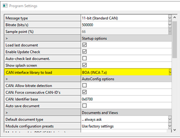
To use ETAS interfaces by CSMconfig, the ETAS BOA driver library must be installed. The required drivers are supplied with the installation of INCA, but can also be downloaded directly from the ETAS download portal.

In order for the ETAS interfaces to be recognized by CSMconfig, the BOA interface library must be selected in the program settings.

Note: Not all ETAS interfaces use the BOA interface. Such interfaces cannot be addressed by CSMconfig despite selection of the BOA interface library.
Program Settings CSMconfig

How do I copy the settings from one module to the next?

To copy a configuration from one module to another module, the following steps must be carried out:

  1. Read existing module chain in CSMconfig.
  2. Switch the modules to offline via the "Online/Offline" button.
  3. Replace the module with the target module (must have identical type).
  4. Switch the modules to online via the "Online/Offline" button.
  5. Change the serial number of the old module by that of the target module.
  6. Write the configuration to the target module.

Why can't every measuring software detect XCP-on-Ethernet Rates higher than 10kHz?

The measurement software must support XCP-DAQ Packed Mode (XCP 1.4 or later).

Why can't the OUTMM be found in CSMconfig?

If the bitrate of the OUTMM is adjusted CSMconfig cannot find the module despite activated bitrate detection in the settings. The OUTMM is completly passive.
If bitrate detection is activated CSMconfig only listens on which bitrate meanigful information is delivered. Since the OUTMM does not send anything CSMconfig cannot recognize the bitrate and does not find the module.

Why do the output levels of the OUTMM deviate at higher ambient temperatures (>85°C)?

The OUTMM has limitations at ambient temperature above 85°C.
You can find these additional deviations which may occur in these temperature ranges in the data sheet.

Why do the ECAT modules work in CSMconfig but not in the measurement software (e.g. CANape, INCA)?

CSMconfig uses a simplified mode for configuration operation. CSMconfig and the XCP-Gateway establish a communication via a special IP adress and a broadcast command.
The measurement software in which the CSM ECAT are integrated does not support this simplified mode. In the measurement software the interface properties (IP adress) must match. If there is a mismatch the measurement sofware cannot communicate with the modules.

What is the effect of disabling a module or channel in CSMconfig?

Deactivating a module or channel has the same effect with CAN as well as with ECAT:

  • the module/channel is no longer listed in the DBC file or A2L file and is therefore not displayed in the measuring software.
  • the module/channel is not taken into account in the "Reconfiguration of all devices" and "Test" functions.
  • the channels are still displayed in CSMconfig. To distinguish from active channels, deactivated channels are displayed grayed out.

But:

  • Deactivated modules/channels do not reduce the bus load. The data is still transmitted.
  • The state is not stored in the measuring module but only displayed graphically.

Where does Config look for firmware files for module updates, i.e. how do you integrate firmware downloads into CSMconfig?

The default path where Config searches for fírmware files depends on the CSMconfig architecture (32/64Bit) and the particular version number.

  • For 32Bit CSMconfig versions (≤V8.15), the following default path is used:
    "C:\Program Files (x86)\CSMconfig*CSMconfig Version*\Firmware\".
  • For 64Bit CSMconfig versions (≥V9.0.0), the following default path is used:
    "C:\Program Files\CSMconfig\*CSMconfig Version*\Firmware\".

Via the firmware update dialog directly in the software, any special path can be specified in which special firmware files may be located.

Firmware Update
CSMconfig Firmware Update

Which adjustment procedures exist in CSMconfig and which effects do they have on the measuring modules?

The following adjustment procedures are available in CSMconfig:

  • Auto-Offset
    The scaling value "Offset" is changed in the configuration document (A2L/DBC).
  • Auto scaling
    The scaling values ""Factor"" and ""Offset"" are changed in the configuration document (A2L/DBC).
  • Zero adjustment
    The zero point is adjusted directly in the measuring module by the zero point adjustment. (By shifting the zero position, the resulting measuring range becomes asymmetrical accordingly) This adjustment has no effect on the scaling values in the configuration document (A2L/DBC). Note: This property is only supported by certain device types. Information on the supported device types can be found in the CSMconfig help under the keyword "Support of module-internal adjustment procedures".
  • Linear Adjustment
    With the linear adjustment, the sensor characteristic stored in the module can be adjusted using two reference measuring points (freely selectable by the user). Note: This feature is only supported by certain device types. Information on the supported device types can be found in the CSMconfig help under the keyword "Support of module-internal adjustment procedures".
  • Bridge Adjustment
    The bridge calibration determines the circuit-dependent value for the zero point calibration of a measuring bridge. This offset value is stored in the measuring module. Note: This adjustment procedure is only available for the STGMM.

How to find out what the warning icons in CSMconfig indicate?

CSMconfig displays certain problems as triangles with exclamation marks in the tree view. The command Check Document offers the possibility to output the warnings as text. If you execute the command, a report in HTML format is created, which points out the background of errors.

Call

  • via the icon in the toolbar Warning symbolor
  • File ➞ Check document.

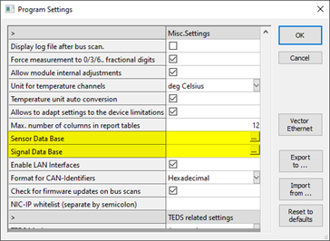
Where can I integrate a sensor or signal database into CSMconfig?

A sensor database is an external file in CSV format. Sensors with their most important parameters are stored in this file. A sensor database serves to simplify the configuration of commercially available sensors.

The signal database is also an external file in CSV format. If the Signals and measuring points are always named the same, the names or comments can be stored in the file. The user then does not have to make the input again manually for each configuration.

In CSMconfig, both files are integrated in the program settings. Changes in the files are automatically accepted after a restart of CSMconfig.
Program Settings CSMconfig

Which TEDS operating modes are there in CSMconfig and what is their meaning?

In CSMconfig there are three different TEDS operating modes, which can be set in the program settings.

  • Not using TEDS:
    The TEDS modules are completely ignored. It is not possible to read in the sensors manually in CSMconfig. The menu item provided for this purpose is not available in this mode.
  • Manual:
    The reading of the TEDS information must be explicitly carried out by the user. If the user does not read in the TEDS information manually, CSMconfig behaves as in the "Do not use" mode.
  • Automatic:
    The TEDS contents are automatically read out in the background when the bus configuration is read in and compared with the module configuration. The transfer of the TEDS information into the configuration document and the module configuration must be initiated manually by the user.

How to check if the module configuration is ok and matches the settings in DBC/A2L file?

The Check document command provides the possibility to check whether

  • the parameters of the active measuring modules contained in the document correspond to the settings of the connected measuring modules.
  • the document or module configuration contains errors and if so, which ones.

If the command is executed, a report in HTML format is created, which points out the differences and errors.

The command can be called via the icon in the toolbar Warning symbol or file ➞ Check document.