FAQ General
Questions and answers on CSM products.
Support 
Questions and answers on CSM products.
CANape automatically uses the installed CSMconfig with the highest version number.
The CANape driver expects exactly defined settings with regard to the network configuration. If an XCP gateway is to be exchanged in an existing CANape project, the new gateway must use identical IP address settings like the replaced gateway. The different serial numbers of the two devices will cause no problem, since the communication between CANape and the modules is identified exclusively via the IP address.
To set the correct connection parameters (IP address), open the "XCP Gateway Configuration" dialog in CSMconfig and adapt it.
Note: If the IP address of the old gateway is not known, there are two ways to find it out.
A complete list of CAN AD modules with TEDS functionality can be found here: Measurement modules with TEDS support
The STGMM 6 CAN and ECAT modules support TEDS (CSM-proprietary template).
Currently not all CAN interfaces available in CSMconfig are supported by CSMview. CAN interfaces from the following manufacturers are currently available for CSMview:
Note
The following BOA driver-based interfaces in CSMview are supported since CSMconfig V8.15:
All module housing dimensions are listed on the CSM website.
These are in detail: Case eXtra Small (CXS), Case Small (CS), Slide Case Small (SCS), Case Large (CL), Slide Case Large (SCL),
1000 V voltage inputs and the associated signal cables can be identified by the color coding.
1. On the cable:
2. On the module:
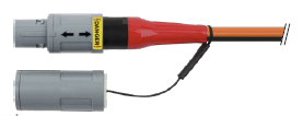
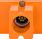
| Pin | Signal | Description | |
|---|---|---|---|
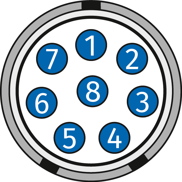
Code B |
1 | V1IN+ | Channel 1 Input voltage, plus (K1 +) |
| 2 | V1IN- | Channel 1 Input voltage, minus (K1 -) | |
| 3 | V2IN+ | Channel 2 Input voltage, plus (K2 +) | |
| 4 | V2IN- | Channel 2 Input voltage, minus (K2 -) | |
| 5 | V3IN+ | Channel 3 Input voltage, plus (K3 +) | |
| 6 | V3IN- | Channel 3 Input voltage, minus (K3 -) | |
| 7 | V4IN+ | Channel 4 Input voltage, plus (K4 +) | |
| 8 | V4IN- | Channel 4 Input voltage, minus (K4 -) |
*For the HV AD8 OW20 the second signal socket is assigned identically to the first socket.
| Pin | Signal | Description | |
|---|---|---|---|
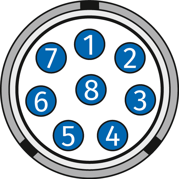
Code D |
1 | V1IN+ | Channel 1 Input voltage, plus (K1 +) |
| 2 | V1IN- | Channel 1 Input voltage, minus (K1 -) | |
| 3 | V2IN+ | Channel 2 Input voltage, plus (K2 +) | |
| 4 | V2IN- | Channel 2 Input voltage, minus (K2 -) | |
| 5 | V3IN+ | Channel 3 Input voltage, plus (K3 +) | |
| 6 | V3IN- | Channel 3 Input voltage, minus (K3 -) | |
| 7 | V4IN+ | Channel 4 Input voltage, plus (K4 +) | |
| 8 | V4IN- | Channel 4 Input voltage, minus (K4 -) |
| Pin | Signal | Description | |
|---|---|---|---|
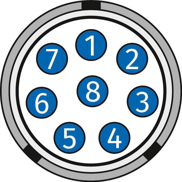
Code C |
1 | V1IN+ | Channel 1 Input voltage, plus |
| 2 | V1IN- | Channel 1 Input voltage, minus | |
| 3 | V1OUT+ | Channel 1 Sensor supply output, plus | |
| 4 | V1OUT- | Channel 1 Sensor supply output, minus | |
| 5 | V2IN+ | Channel 2 Input voltage, plus | |
| 6 | V2IN- | Channel 2 Input voltage, minus | |
| 7 | V2OUT+ | Channel 2 Sensor supply output, plus | |
| 8 | V2OUT- | Channel 2 Sensor supply output, minus |
*For the HV AD8 OW20 the further signal socket is assigned identically to the first socket.
| Pin | Signal | Description | |
|---|---|---|---|

Code B |
1 | K1+ | Channel 1 Input voltage, plus |
| 2 | K1- | Channel 1 Input voltage, minus | |
| 3 | K2+ | Channel 2 Input voltage, plus | |
| 4 | K2- | Channel 2 Input voltage, minus | |
| 5 | K3+ | Channel 3 Input voltage, plus | |
| 6 | K3- | Channel 3 Input voltage, minus | |
| 7 | K4+ | Channel 4 Input voltage, plus | |
| 8 | K4- | Channel 4 Input voltage, minus |
*For the HV TH8 and HV TH TBM8, the second signal socket is assigned identically to the first socket.
| Pin | Signal | Description | |
|---|---|---|---|

Code C |
1 | V1IN+ | Channel 1 Input voltage, plus |
| 2 | V1IN- | Channel 1 Input voltage, minus | |
| 3 | I1OUT+ | Channel 1 Sensor supply output (current), plus | |
| 4 | I1OUT- | Channel 1 Sensor supply output (current), minus | |
| 5 | V2IN+ | Channel 2 Input voltage, plus | |
| 6 | V2IN- | Channel 2 Input voltage, minus | |
| 7 | I2OUT+ | Channel 2 Sensor supply output (current), plus | |
| 8 | I2OUT- | Channel 2 Sensor supply output (current), minus |
*For the HV PT TBM8, the other signal sockets are assigned identically to the first socket.
| Pin | Signal | Description | |
|---|---|---|---|
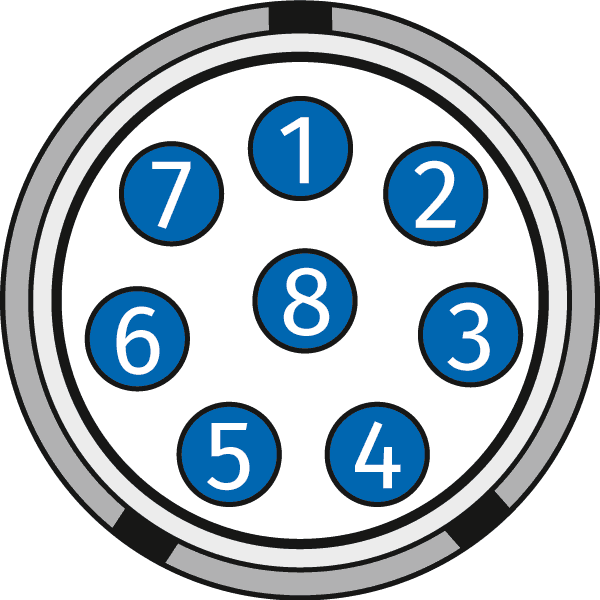
Code E |
1 | VIN+ | Input voltage plus |
| 2 | VIN- | Input voltage minus | |
| 3 | VOUT+ | Bridge excitation voltage plus | |
| 4 | VOUT- | Bridge excitation voltage minus | |
| Channel shield | Shield for measurement signal | ||
| 5 | VSENSE+ | Sense plus | |
| 6 | VSENSE- | Sense minus | |
| 7 | TEDS GND | TEDS Ground | |
| 8 | TEDS Data | TEDS Data line |
*For the HV STG4 pro BS20, the other signal sockets are assigned identically to the first socket.
| Pin | Signal | Description | |
|---|---|---|---|

Code C |
1 | x-axis | Measurement signal for the x-axis |
| 2 | y-axis | Measurement signal for the y- axis | |
| 3 | z-axis | Measurement signal for the z- axis | |
| 4 | GND | Ground of measurement signal | |
| 5 | n.c. | Not connected | |
| 6 | n.c. | Not connected | |
| 7 | n.c. | Not connected | |
| 8 | n.c. | Not connected |
To connect IEPE (ICP sensors) to ECAT ADMM, the following variants are available depending on the type of sensor supply of the measuring module.
| K645 | L1B 8p, BNC | for unipolar sensor supply (Vout >20V required) |
| K667 | L1B 8p, BNC | for bipolar sensor supply (only for galvanically isolated sensor supply in the module) |
| K664 | Fischer variant of K667 |
Information on cables and general CAN or ECAT accessories can be found here.
For more detailed technical questions contact support@csm.de. If you have further questions about CSM products in general, please contact your personal account manager or sales@csm.de.
The CSMcan can be used with the following software products:
The CSMcan is not supported in CANape and cannot therefore be used as an interface.
The TEDS module can only be read out if the measuring bridge has been connected correctly. This can be recognized by the green channel LED. As long as this does not light up green, the TEDS cannot be read out either.
The MiniModules for strain gauge measurements (STGMM) require the 6-wire technology.
If a sensor with 4-wire technology is used, the sense wires must be connected to the supply voltage of the measuring bridge (Vsense+ to Vout+ / Vsense- to Vout-).
In addition, the module should be updated to the latest firmware version. The latest firmware is supplied with the latest CSMconfig or can be found on the homepage.
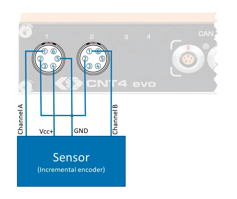
Incremental encoders with direction detection via A/B channels are connected to the CNT4 MiniModule via two consecutive channels.
The two pulse signals of the incremental encoder are detected by the signal inputs of the respective channel on the CNT. Interm in the module, the counting direction is detected and the counting result is sent on the bus.
| Connector Measuring input/measurement bridge | Pin (Cable K642) | Signal | Cable Colour | Description |
|---|---|---|---|---|
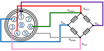
|
1 | V IN - | violet | Input voltage, minus |
| 2 | V IN + | blue | Input voltage, plus | |
| 3 | V OUT - | pink | Bridge excitation voltage, ground | |
| 4 | V OUT + | red | Bridge excitation voltage, plus | |
| 5 | V SENSE - | grey | Sense Minus | |
| 6 | V SENSE + | green | Sense Plus | |
| 7 | TEDS GND Channel Shield |
Standard drain | TEDS Ground Shield for measurement signal |
|
| 8 | TEDS DATA | yellow | Data line (TEDS) | |
| Housing | Cable Shield | Shield | Outer Shield (Housing) |
| Connector Measuring input/measurement bridge | Pin (Cable K642) | Signal | Cable Colour | Description |
|---|---|---|---|---|
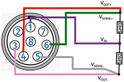
|
1 | V IN - | violet | Input voltage, minus |
| 2 | V IN + | blue | Input voltage, plus | |
| 3 | V OUT - | pink | Bridge excitation voltage, ground | |
| 4 | V OUT + | red | Bridge excitation voltage, plus | |
| 5 | V SENSE - | grey | Sense Minus | |
| 6 | V SENSE + | green | Sense Plus | |
| 7 | TEDS GND Channel Shield |
Standard drain | TEDS Ground Shield for measurement signal |
|
| 8 | TEDS DATA | yellow | Data line (TEDS) | |
| Housing | Cable Shield | Shield | Outer Shield (Housing) |
| Connector Measuring input/measurement bridge | Pin (Cable K356) | Signal | Cable Colour | Description |
|---|---|---|---|---|
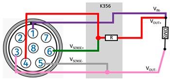
|
1 | V IN - | violet | Input voltage, minus |
| 2 | V IN + | blue | Input voltage, plus | |
| 3 | V OUT - | pink | Bridge excitation voltage, ground | |
| 4 | V OUT + | red | Bridge excitation voltage, plus | |
| 5 | V SENSE - | grey | Sense Minus | |
| 6 | V SENSE + | green | Sense Plus | |
| 7 | TEDS GND Channel Shield |
Standard drain | TEDS Ground Shield for measurement signal |
|
| 8 | TEDS DATA | yellow | Data line (TEDS) | |
| Housing | Cable Shield | Shield | Outer Shield (Housing) |
With the software LicenseUploader, options purchased after delivery can be uploaded to the respective measurement module. You can find the software in the download area.
The following options can be uploaded to the measurement modules with this software:
All other options, e.g. concerning the XCP-Gateway are written to the modules via CSMconfig.
The input impedance of the HV AD4 XW20 is similar to HV AD4 XW1000 (there it is already written in the datasheet): approx. 9 MΩ / approx. 20 pF.