FAQ CAN
Questions and answers on CSM CAN Modules.
Support 
Questions and answers on CSM CAN Modules.
The pin assignment of the corresponding signal socket for the ECAT modules can be found in the two documents "ECAT STGMM6" and "ECAT ADMM4 HS", which are located under Help at CSMconfig.
| Connector Measuring input | Pin | Signal | Description |
|---|---|---|---|
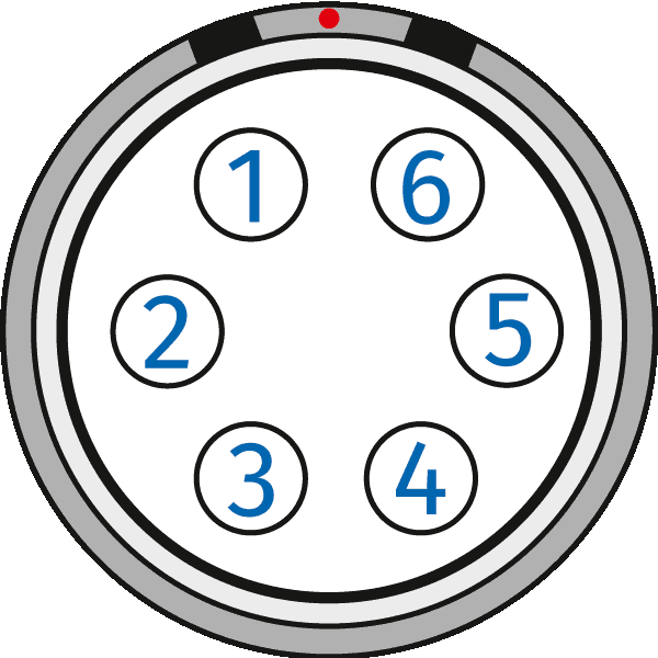
LEMO 0B, 6pol |
1 | VIN + | Input voltage, plus |
| 2 | VIN - | Input voltage, minus | |
| 3 | -- | reserved, do not connect | |
| 4 | VOUT + | Sensor supply output, plus | |
| 5 | VGND | Sensor supply ground | |
| 6 | VOUT - | Sensor supply output, minus |
| Connector Measuring input | Pin | Signal | Description |
|---|---|---|---|

LEMO 0B, 6pol |
1 | VIN + | Input voltage, plus |
| 2 | VIN - | Input voltage, minus | |
| 3 | -- | reserved, do not connect | |
| TEDS Data | TEDS Data line | ||
| 4 | VOUT + | Sensor supply output, plus | |
| 5 | VGND | Sensor supply ground | |
| TEDS GND | TEDS Ground (additional) | ||
| 6 | VOUT - | Sensor supply output, minus | |
| -- | reserved, do not connect1 |
1 Only for measurement modules ADMM 4/AD4 MX2
| Connector Measuring input | Pin | Signal | Description |
|---|---|---|---|

LEMO 0B, 6pol |
1 | VIN + | Input voltage, plus |
| 2 | VIN - | Input voltage, minus | |
| 3 | -- | reserved, do not connect | |
| 4 | VOUT + | Sensor supply output, plus | |
| 5 | VGND | Sensor supply ground | |
| 6 | -- | reserved, do not connect |
| Connector Measuring input |
Pin | Signal | Description |
|---|---|---|---|

LEMO 0B, 6pol |
1 | VIN + | Input voltage, plus |
| 2 | VIN - | Input voltage, minus | |
| 3 | -- | reserved, do not connect | |
| 4 | IOUT + | Sensor supply output, plus | |
| 5 | IOUT - | Sensor supply output, minus | |
| 6 | -- | reserved, do not connect |
| Connector Measuring input | Pin | Signal | Description |
|---|---|---|---|
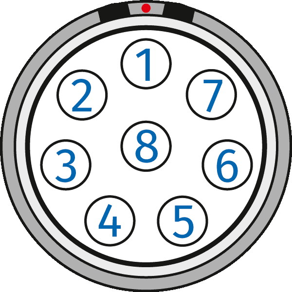
LEMO 1B, 8pol |
1 | VIN - | Measured voltage, minus |
| 2 | VIN + |
Measured voltage, plus | |
| 3 | VOUT - | Bridge excitation voltage, ground | |
| 4 | VOUT + | Bridge excitation voltage, plus | |
| 5 | VSENSE - | Sense minus | |
| 6 | VSENSE + | Sense plus | |
| 7 | TEDS GND | TEDS Ground | |
| Channel Shield | Shield for measurement signal | ||
| 8 | TEDS Data | TEDS Data line | |
| Housing | Cable Shield | Outer Shield (housing) |
| Connector Measuring input |
Pin | Signal | Description |
|---|---|---|---|
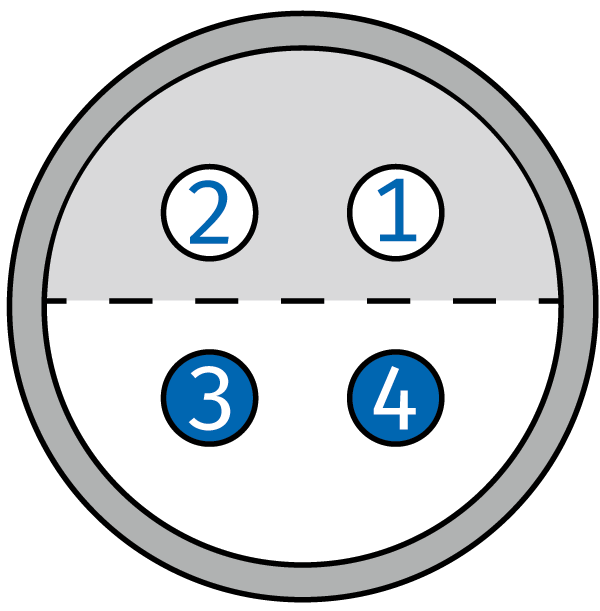
LEMO 1S, 4pol (FFA.1S.304.CLAC.42ZN) |
1 | IOUT + | Sensor supply output, plus |
| 2 | VIN + | Input voltage, plus | |
| 3 | IOUT - | Sensor supply output, minus | |
| 4 | VIN - | Input voltage, minus | |
| Chassis | Shield | Shield |
| Connector Measuring input | Pin | Signal | Description |
|---|---|---|---|
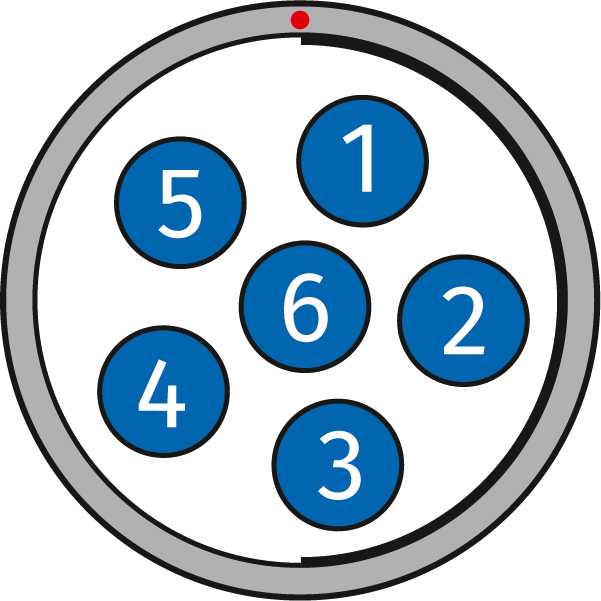
Fischer, 6pol |
1 | -- | Reserved, do not connect |
| 2 | VIN - | Input voltage, minus | |
| 3 | IOUT + | Sensor supply output, plus | |
| 4 | IOUT - | Sensor supply output, minus | |
| 5 | VIN + | Input voltage, plus | |
| 6 | -- | Reserved, do not connect |
| Connector Measuring input | Pin | Signal | Description |
|---|---|---|---|
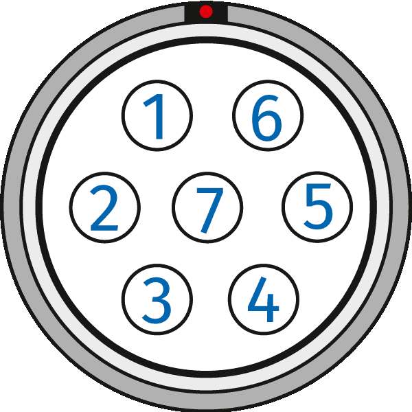
LEMO 1B, 7pol |
1 | VIN + | Input voltage, plus |
| 2 | -- | -- | |
| 3 | VIN - | Input voltage, minus | |
| 4 | VOUT + | Sensor supply output, plus | |
| 5 | VGND | Sensor supply ground | |
| 6 | -- | -- | |
| 7 | -- | -- |
| Connector Measuring input | Pin | Signal | Description |
|---|---|---|---|

LEMO 1B, 7pol |
1 | VIN + |
Input voltage, plus |
| 2 | V OUT + |
Sensor supply output, plus | |
| 3 | -- | -- | |
| 4 | -- | -- | |
| 5 | VOUTGND | Sensor supply ground | |
| 6 | V IN - |
Input voltage, minus | |
| 7 | -- | -- |
| Connector Measuring input | Pin | Signal | Description |
|---|---|---|---|

Fischer, 6pol |
1 | Shield | Connected to case |
| 2 | V IN - |
Input voltage, minus | |
| 3 | V OUT + |
Sensor supply, plus | |
| 4 | VGND | Sensor supply ground | |
| 5 | VIN + | Input voltage, Plus | |
| 6 | V OUT - |
Sensor supply output, minus |
| Connector Measuring input | Pin | Signal | Description |
|---|---|---|---|

LEMO 1B, 7pol |
1 | VIN + |
Input voltage, plus |
| 2 | V OUT + |
Sensor supply output, plus | |
| 3 | -- | -- | |
| 4 | -- | -- | |
| 5 | VOUT - | Sensor supply output, minus | |
| 6 | V IN - |
Input voltage, minus | |
| 7 | VOUTGND | Sensor supply ground |
Usually, the CAN-ID for CSM measurement modules is defined for a group of channels. Often valid for the entire module. This then occupies a consecutive range of CAN identifiers.
For some measurement modules, however, the CAN identifier and transmission rate can also be specified per channel. CAN identifiers can be defined channel by channel individually. However, the format (11/29 bit) must correspond to the CAN bus definition.
The option to define CAN identifier and transmission rate per channel is activated in the "Device Configuration" dialog or in the "Device List" view.
Restrictions for single channel configuration:
The AD MM series measures the input voltage (=> output voltage of the sensor) using VIN + and VIN - . These PINs are isolated from the rest of the module and have no defined potential unless a sensor is connected.
Since sensors measure the output voltage relative to the sensor ground, VIN- must also be connected to the sensor ground.
| Connector measuring input | Pin | Signal (unipolar sensor supply) |
Signal (bipolar sensor supply) |
Description |
|---|---|---|---|---|
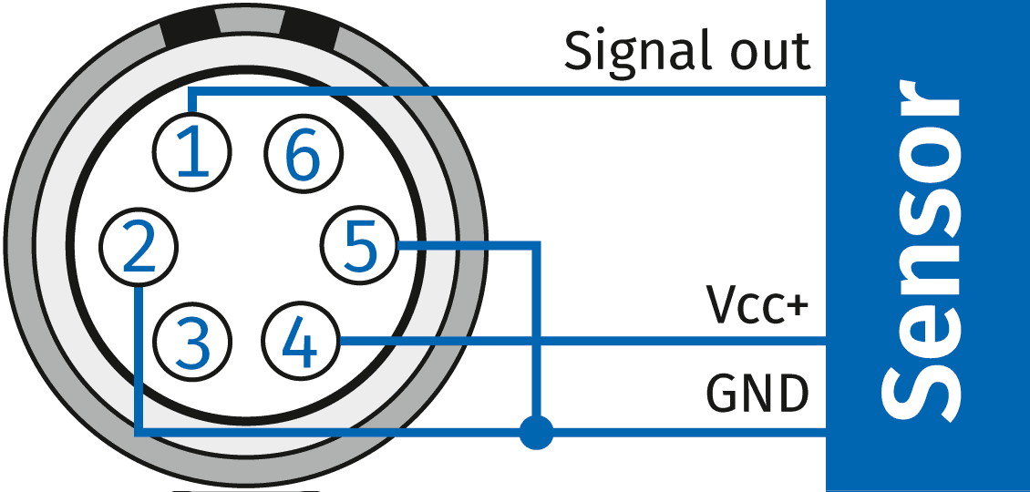
LEMO 0B, 6pol |
1 | VIN + | VIN + | Input voltage, positive |
| 2 | VIN - | VIN - | Input voltage, negative | |
| 3 | -- | -- | Reserved, not connected | |
| 4 | VOUT + | VOUT + | Sensor supply output, positive | |
| 5 | VGND | VGND | Sensor supply ground | |
| 6 | -- | VOUT - | Sensor supply output, negative |
| Connector measuring input | Pin | Signal (unipolar sensor excitation) |
Signal (bipolar sensor excitation) |
Descritption |
|---|---|---|---|---|
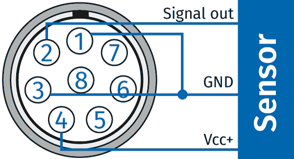
LEMO 1B, 8pol |
1 | VIN - | VIN - | Input voltage, negative |
| 2 | VIN + |
VIN + |
Input voltage, positive | |
| 3 | VGND | VGND | Sensor supply ground | |
| 4 | VOUT + | VOUT + | Sensor supply output, positive | |
| 5 | - | VOUT - | Sensor supply output, negative | |
| 6 | - | - | Reserved, not connected | |
| 7 | Channel Shield | Channel Shield | Shield for measurement signal | |
| 8 | Data | Data | Data line (TEDS) | |
| Housing | Cable Shield | Cable Shield | Outer Shield (housing) |
This function is only available for the following CAN module types:
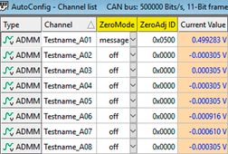
To be able to use this function, it must be activated in the program settings of CSMconfig. Open the settings and activate the following entry: Allow module internal adjustment procedures. The adjustment of the zero point takes place (and only with this AD MM) in the module. This means that changing the offset setting does not change the DBC file.
In CSM config you have two possibilities to recognize the used CAN message for the zero adjustment and to change it, if necessary.

The difference in the measuring ranges depends on the module type.
AD CAN MM-Series (ADMM classic): ±100, ±200, ±500 mV and ±10, ±20, ±60 V
AD pro CAN MM-Series (ADMM pro/pro2): ±10, ±20, ±50, ±100, ±200, ±500 mV and ±1, ±2, ±5, ±10, ±20, ±60 V
Further differences between the modules of the AD CAN MM-Series and AD pro CAN MM-Series can be found in the data sheets on the homepage.
The writing of channel comments is not supported by all measurement modules.
This feature is currently supported by the following module types:
Unlike the ADMM CAN, the STGMM CAN does not react to a message with any content. The CAN message, which is to trigger the calculation of the zero offset for the respective channel in the measurement module, must have the following content:
| Module type | DLC | Byte 0 | Byte 1 | Byte 2 | Byte 3 | Byte 4 | Byte 5 | Byte 6 | Byte 7 |
|---|---|---|---|---|---|---|---|---|---|
| STG CAN MM | 8 | 0 | 0 | 0 | 0 | 0x7A | 0x65 | 0x72 | 0x6F |
The CAN modules are supplied with voltage via the bus. For this reason, the measurement stops as soon as the modules are disconnected from the bus. If the connection between the CAN bus and the module is re-established, the modules measure and transmit normally.
The IDs used are only visible in CSMconfig if the expert mode is activated. The expert mode is activated via the system menu in the header bar. The system menu opens with a click on the program icon on the left in the header bar. The expert mode can be activated here.
After activating the expert mode, the CAN IDs are available in the channel settings. To display them in the columns, the flag "CAN" must be set in the channel settings.
The modules expect values in the range of -50 to +500°C. If a value is outside the range, a sensor break is detected.
The CSMshunt passive allows a temporary overcurrent of 10A.
As with all CSMshunts, this current may only be applied for a maximum of 5 seconds.
The permissible overcurrent for the CSM shunt 500 open passive depends on the duration of the current:
The measuring amplifier of the shunt has a gain factor that is adapted to the current range. It outputs a voltage of 10V at 25A. A higher voltage than 10V cannot be output by the measuring amplifier. Short-term peaks are therefore cut off.
An STGMM measuring module can measure very small signals if the noise component of the input signal is reduced by using a filter (Butterworth, cut-off frequency max. 100 Hz). CSMconfig can detect such cases and then adjusts the list of possible filter frequencies. However, higher filter frequencies are only available when larger measuring ranges are used.
The lower limit value for the start of a reduced measuring range depends on certain parameters. The following table summarizes a few examples.
| Sensor excitation | STG settings | Reduced Range | Regular Range |
|---|---|---|---|
| 1,0 V | - | 3,0 .. 20 mV/V | 20 .. 200 mV/V |
| 2,5 V | - | 1,2 .. 8 mV/V | 8 .. 80 mV/V |
| 5,0 V | - | 0,6 .. 4 mV/V | 4 .. 40 mV/V |
| 2,5 V | B=1,3, k=2,05 | 1801 .. 12007 µm/m | 12007 .. 120075 µm/m |
| 5,0 V | B=4, k=2,05 | 229 .. 1951 µm/m | 1951 .. 19512 µm/m |
| 5,0 V | B=2, k=4,0 | 300 .. 2000 µm/m | 2000 .. 20000 µm/m |
The modules CSMpressure, LambdaCANc and NOxCAN use the CANopen protocol. The CANopen standard already covers some IDs for internal communication purposes. For this reason, the entire ID range cannot be set.
Preallocated and therefore blocked IDs are the following:
| // Reserve 0x0 | --> NMT (network management) |
| // Reserve 0x80-0xFF | --> Error-messages |
| // Reserve 0x580-0x5FF / 0x600-0x67F | --> SDO communication |
| // Reserve 0x700-0x77F | --> Heart Beat |
| // Reserve 0x7E4-0x7E5 | --> LSS (Layer Settings Services) |
By default CSMconfig starts with the CAN-ID assignment at 0x600. As soon as CANopen modules are included in the configuration, the basic CAN ID shifts automatically to 0x680.
The "Info message" option can be used to send signals about the device type, device status, software version as well as serial number and the internal temperature of the measuring module. The data are transmitted in a separate message (additional bus load).
Representation of the signals in the measuring software:
Info message
| Signalname | Description | CSM CAN modules (without HV BM) | HV BM modules |
|---|---|---|---|
| _devicename_Device | Name of the device | X | X |
| _devicename_SN | Serial number | X | X |
| _devicename_Status | Status information | X | X |
| _devicename_Major | Firmware number before the dot | X | - |
| _devicename_Minor | Firmware number after the dot | X | - |
| _devicename_PTLo | Internal temperature of the module (not supported by all modules) |
X | - |
| _devicename_Temp_Dev | Device temperature | - | X |
| _devicename_Tep_Shunt | Shunt temperature | - | X |
BM Temperatures
| Signal name | Description |
|---|---|
| _devicename_Temp_Shield | Shunt temperature for the shunt of the shield measurement |
| _devicename_Temp_L1 | Shunt temperature phase 1 |
| _devicename_Temp_L2 | Shunt temperature phase 2 |
| _devicename_Temp_L3 | Shunt temperature phase 3 |
A calibration interval of 12 months is recommended.
With zero adjustment via CAN message, the currently applied measured value is used (no mean value or similar.). The user must observe the system and ensure that the input measurement values do not oscillate and that the system behaves "quietly". Noise can falsify the zeroing.
| Connector Measuring Input | Pin | Signal | Description |
|---|---|---|---|
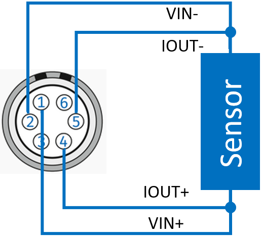
LEMO 0B, 6pol |
1 | VIN + | Input voltage, plus |
| 2 | VIN - | Input voltage, minus | |
| 3 | -- | reserved, do not connect | |
| 4 | IOUT + | Sensor supply output, plus | |
| 5 | IOUT - | Sensor supply output, minus | |
| 6 | -- | reserved, do not connect |
| Connector Measuring Input | Pin | Signal | Description |
|---|---|---|---|
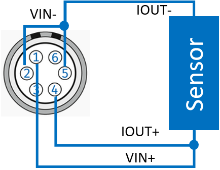
LEMO 0B, 6pol |
1 | VIN + | Input voltage, plus |
| 2 | VIN - | Input voltage, minus | |
| 3 | -- | reserved, do not connect | |
| 4 | IOUT + | Sensor supply output, plus | |
| 5 | IOUT - | Sensor supply output, minus | |
| 6 | -- | reserved, do not connect |
| Connector Measuring Input | Pin | Signal | Description |
|---|---|---|---|
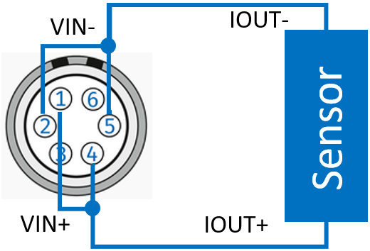
LEMO 0B, 6pol |
1 | VIN + | Input voltage, plus |
| 2 | VIN - | Input voltage, minus | |
| 3 | -- | reserved, do not connect | |
| 4 | IOUT + | Sensor supply output, plus | |
| 5 | IOUT - | Sensor supply output, minus | |
| 6 | -- | reserved, do not connect |
The pin assignment of the CAN sockets of CAN modules can be found in the "MiniModule manual", which is located under Help at CSMconfig.
| Connector Measuring input | Pin | Signal | Description |
|---|---|---|---|
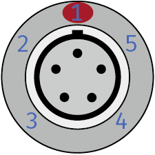
LEMO 0B, 5pol |
1 | Power + | Power Supply plus |
| 2 | Power GND | Power Supply ground | |
| 3 | CAN_H | CAN high | |
| 4 | CAN_L | CAN low | |
| 5 | CAN_GND | CAN ground | |
| Chassis | Cable Shield | Cable Shield |
| Connector Measuring input | Pin | Signal | Description |
|---|---|---|---|

Fischer 7pol |
1 | -- | reserved, do not connect |
| 2 | CAN_H | CAN high | |
| 3 | CAN_L | CAN low | |
| 4 | Power + | Power Supply plus | |
| 5 | Power + | Power Supply plus | |
| 6 | Power GND | Power Supply ground | |
| 7 | Power GND | Power Supply ground | |
| Chassis | Cable Shield | Cable Shield |
The difference in the IP protection class of the CSMshunt is due to the following reasons: