HV BM-Split evo
Measurement of voltage and current from the inner conductor in high-voltage (HV) electrical systems
The HV BM-Split evo use the proven technology of the HV Breakout Modules for fast and precise measurement of current, voltage and power from the inner conductor of a high-voltage power cable. These modules can be conveniently installed thanks to the separation into breakout boxes and a measurement module.
- Measurement of voltage (U) and current (I) in HV applications
- For working voltages up to ±1,000 V (measurement range up to ±2,000 V)
- For currents up to ±1,000 A (nominal), ±2,000 A (peak)
- Synchronous acquisition of current and voltage
- Measurements in copper or aluminum cables
- Simultaneous EtherCAT® and CAN bus communication
- Output of voltage and current, each with a measurement data rate of up to 2 MHz
- Optional output of RMS values of current and voltage as well as active power, reactive power, apparent power and power factor via CAN bus
Overview HV BM-Split evo
The HV BM-Split evo is an important component of the Vector CSM E-Mobility Measurement System and serves as a basis for a wide range of measurement applications. They are used where there is insufficient space to install the HV Breakout Modules.
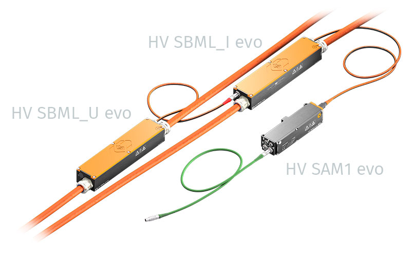
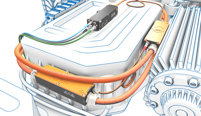
The HV BM-Split evo consists of three components for flexible installation:
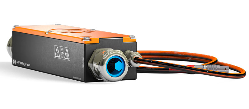
- Breakout boxes with shunt modules for current measurement
- Breakout boxes or cables for voltage tapping
- Measurement modules for acquiring the measured values
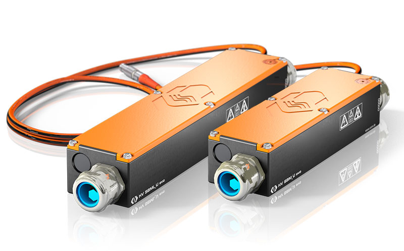
The breakout boxes and/or sensor cables are connected to each other with shielded, HV-safe sensor cables and connected to the input of the HV SAM1 evo. The variants with “L” in the naming convention (HV SBML_U evo and HV SBML_I evo) are used specifically for measurements on HV aluminum cables. All breakout boxes in the evo series also feature an isolated feedthrough for the HV cable shielding inside the breakout box.
The "split" design allows the individual breakout boxes and the HV SAM1 evo to be installed wherever space is available.
Current measurement
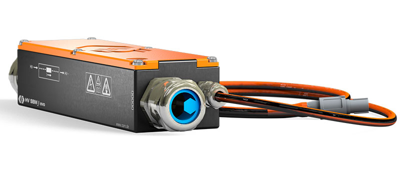
The HV SBM evo measure single-phase currents, whereby the shunts have a temperature sensor for automatic temperature compensation. The shunt-based measurement principle thus provides precise measurement results and can be individually adapted to the respective measurement task. The HV SAM1 evo and HV SBMs are calibrated separately so that they can deployed independently, rather than kept as a matched set.
The shunt modules installed in the HV SBM_I evo and HV SBML_I evo are available for different amperage ranges, allowing them to be chosen for the specific measurement task.
The HV cables are connected inside the device via ring terminals.
Voltage tapping
The HV voltage is tapped in the breakout boxes HV SBM_U evo or HV SBML_U evo. Alternatively, an HV-safe sensor cable with an open end can be used, provided safe installation techniques are followed. The voltage is measured in the HV SAM1 evo measurement module.
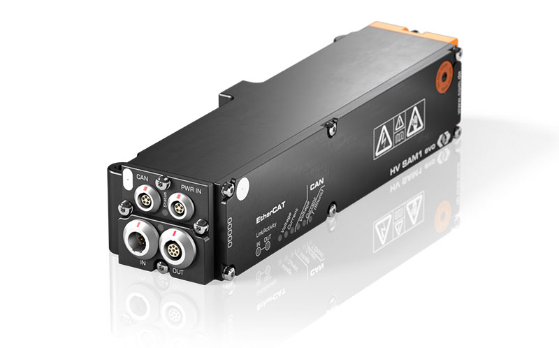
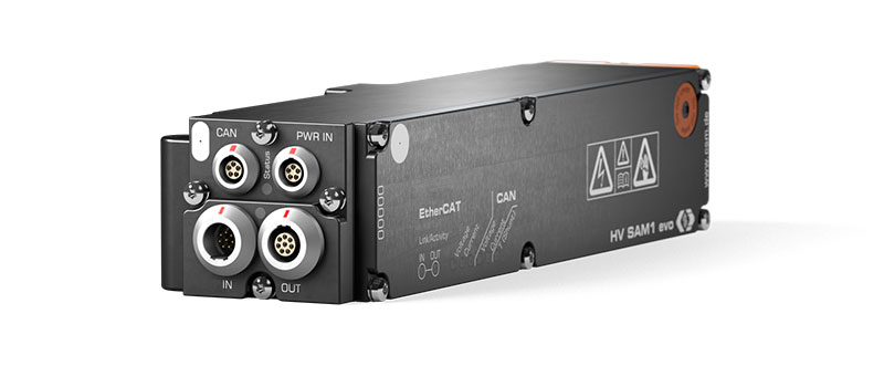
Measurement Module HV SAM1 evo
The HV SAM1 evo measurement module performs data acquisition, filtering, sensor supply, temperature compensation and calculations. It has a signal socket for connecting the sensor cable of the HV SBM_I evo or HV SBML_I evo breakout boxes. Data transfer is via the EtherCAT® interface with a data rate of up to 2 MHz per measurement channel or via a CAN interface.
In addition, the highly precise calculated RMS values of current and voltage as well as active power, apparent power, reactive power and power factor can be transmitted via CAN.
Overview
Breakout boxes modules HV SBM evo
| Designation | Measurement of | Cable connection | Connection | |
|---|---|---|---|---|
| Inner conductor current Rated current |
Nominal voltage Measurement in HV SAM |
Sensor cables permanently installed in HV SBM evo |
||
| HV SBM_I evo HV SBML_I evo |
±50 to ±1,000 A Four configurable measurement ranges, depending on shunt module used. |
Tap HV- | 1 ring terminal per side |
1 sensor cable to HV SAM1 evo |
| HV SBM_U evo HV SBML_U evo |
- | Tap HV+ | 1 ring terminal per side |
1 sensor cable to HV SBM_I evo / HV SBML_I evo |
Click on the corresponding module designation for more information.
Applications
With the HV BM-Split evo, currents and voltages can be measured precisely and at high data rates even when there is insufficient space for the installation of HV Breakout Modules. This means that measurements can be performed even in the installed HV cables on vehicles. This also considerably simplifies the benchmarking of electric vehicles.
HV BM-Split evo always use an HV SAM1 evo to which other breakout boxes can be flexibly connected depending on the task. For HV power cables made of aluminum or copper, the HV SBML_I evo and HV SBML_U evo can be used, and for copper cables, the HV SBM_I evo and HV SBM_U evo is appropriate. Depending on the expected current, a variety of shunt modules can be selected.
The measurement data obtained from the HV BM-Split evo and the eMobilityAnalyzer from the Vector CSM E-Mobility Measurement System can be used to perform a wide range of analyses in real time enabling measurement of the DC power of the inverter of the electric motor, harmonic, PWM, ripple analysis and many more.
Further Information
-
CSM Xplained: Testing of fuel cell drives on test benches and in road testing
-
CSM Xplained: Maintenance of HV measurement technology – calibration and insulation-test
-
CSM Xplained: The Vector CSM E-Mobility Measurement System
-
CSM Xplained: Voltage measurement in e-mobility
-
CSM Xplained: Current measurement in e-mobility
-
CSM Xplained: Autonomous power measurement in road tests and on test benches
Downloads
- Configuration software for CSM measurement modules (incl. documentation)
- with visualization software CSMview
- System requirements:

 Home
Home Newsletter


