Home
Home Newsletter
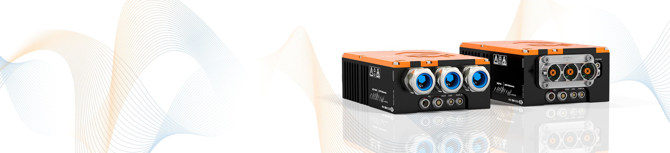
HV Breakout Modules 3.3, 3.3C
Three-phase measurement of internal conductor current and voltage with direct XCP-on-Ethernet output
The HV Breakout Modules (BM) Type 3.3 have been specially designed for safe and precise three-phase measurement in HV power cables. The inner conductor currents and outer conductor voltages are directly acquired and output via XCP-on-Ethernet.
Highlights
- Synchronous measurement of voltages U12, U23, U31 and internal conductor currents (I) of L1, L2, L3 in HV applications
- Voltages up to ±1,000 V (measurement range up to ±2,000 V)
- Currents up to ±800 A (rated ), ±1,400 A (peak)
- GBit/s XCP-on-Ethernet interface, measurement data rate up to 2 MHz per measured variable
- Options:
- XCP-Gateway: Connection of CSM ECAT (fully time-synchronous) and CAN measurement modules
- PTP Slave
- Optional calculation of power and RMS values directly in the module and output via XCP-on-Ethernet and CAN
- In-depth online power analysis with the Vector eMobilityAnalyzer software

Description
HV Breakout Module 3.3 can be used to perform three-phase power measurements directly in HV power cables.
For this purpose, the HV Breakout Module 3.3 is inserted directly into the HV power cables by feeding the cables through cable glands into the interior of the module and connecting them there using ring terminals.
The HV Breakout Module 3.3C is connected to the cables via a PowerLok connector system and is interlock capable.
The outer conductor voltages are measured directly. Current measurement is carried out via shunt modules which contain, among other things, a temperature sensor and a memory for calibration data for automatic online temperature compensation.
The sampling of voltage and current with immediate digitization in the aluminum housing of the HV Breakout Module provides optimum protection against electromagnetic interference.
Calculation of power and RMS values
With the Option Calculated Channels active, apparent and reactive power, power factor as well as the RMS values for current and voltage can be calculated directly in the module from the sampled measured values. Via XCP-on-Ethernet and CAN the calculated values are directly transmitted to the measurement computer or a data logger.
Technical Data
| HV Breakout Module Type 3.3 | HV Breakout Module Type 3.3C | |
|---|---|---|
| Inputs | HV power cable for each phase | |
| Number of measured phases | 3 | |
| HV+/HV- power cable connection | Ring terminals (via cable glands) |
PL300 plug-in system |
| Number of cable glands | 3 per side |
- |
| Cable outer diameter | 9 mm to 25 mm See datasheet |
- |
| Measurement signals | Inner conductor current and voltage | |
| Inner conductor current (rated current) |
From ±500 to ±800 A Four configurable measurement ranges, depending on shunt module used. See datasheet. |
|
| Voltage | ±200, ±500, ±1,000, ±2,000 V For the acquisition of transient overvoltage, the measuring range is dimensioned to ±2,000 V. |
|
| Measurement data rate | ||
| XCP-on-Ethernet | 1, 2, 5, 10, 20, 50, 100, 200, 500, 1,000, 2,000 kHz | |
| CAN | 1, 2, 5, 10, 20, 50, 100, 200, 500 Hz, 1, 2, 5 kHz | |
| Output signals | ||
| XCP-on-Ethernet/CAN | Voltage, current With option Calc. additionally: RMS values for voltage and current, active power, apparent power, reactive power and power factor Lambda |
|
| Integration time RMS value and power calculation | 10 ms to 10 s | |
| Operating conditions | ||
| Housing protection class | IP67 | |
| Operating temperature range | -40°C to +120°C | |
| Pollution degree | 4 | |
XCP-Gateway Options
The measurement modules include an internal XCP gateway. Various options make it easy to expand the module to meet specific requirements.
| Designation | PTP / IEEE1588 | CSM PAK AddOn | XCP-Gateway |
|---|---|---|---|
| HV BM 3.3 and 3.3C | * |
* Included when activating the XCP-Gateway option


Applications
The two versions of the HV Breakout Module 3.3 enable the electrical power measurement of electric vehicle motors. The modules are particularly suitable for mobile real-time measurements in the high-voltage electrical system of test vehicles.
The three-phase measurement with only one measurement device offers enormous installation, cost and space advantages.
The direct output of power and RMS values allows various analyses without the use of special hardware and software in the road test. More in-depth analyses, such as the investigation of leakage currents and symmetries as well as the correlation with measured values from further CSM measurement modules (e.g. temperatures) can be performed with the Vector CSM E-Mobility Measurement System.

Further Information
-
CSM Xplained: Testing of fuel cell drives on test benches and in road testing
-
CSM Xplained: Maintenance of HV measurement technology – calibration and insulation-test
-
CSM Xplained: The Vector CSM E-Mobility Measurement System
-
CSM Xplained: Voltage measurement in e-mobility
-
CSM Xplained: Current measurement in e-mobility
-
CSM Xplained: Autonomous power measurement in road tests and on test benches