Home
Home
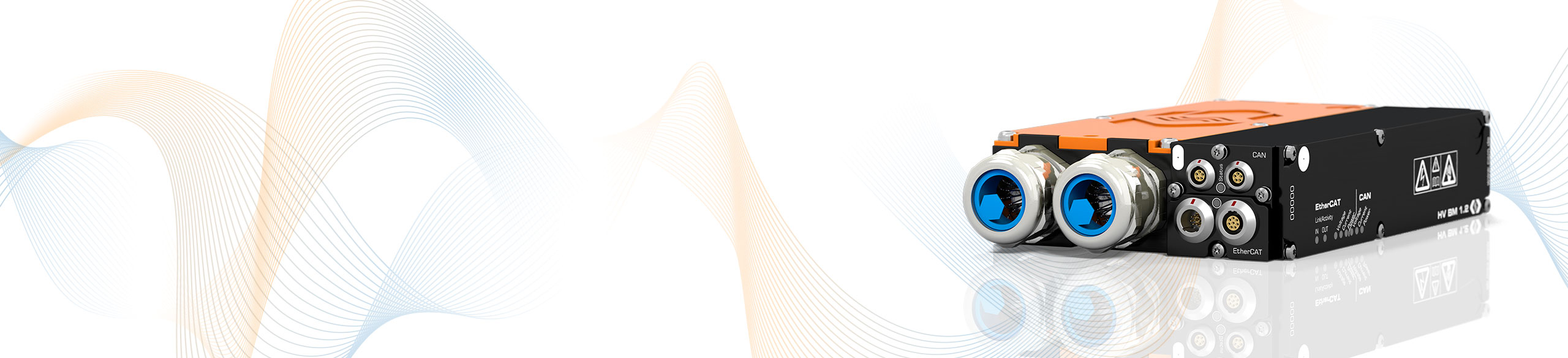
HV Breakout Modules 1.2
Single-phase measurement of internal conductor current and voltage
The HV Breakout Modules (BM) Type 1.2 have been specially designed for safe and precise single-phase measurement in separated HV+ and HV- power cables. Inner conductor current and voltage are measured directly and the instantaneous power is calculated in the module.
Highlights
-
- Measurement of voltage (U) and internal conductor current (I) in HV applications
- Voltages up to ±1,000 V (measurement range up to ±2,000 V)
- Currents up to ±1,000 A (rated), ±2,000 A (peak)
- Calculation of the instantaneous power in the module
- Simultaneous EtherCAT® and CAN bus communication
- Output of voltage, current and instantaneous power with up to 1 MHz measurement data rate each
- Measurement of voltage (U) and internal conductor current (I) in HV applications
- Optional calculation of power and RMS values directly in the module and output via CAN
- In-depth online power analysis with the Vector eMobilityAnalyzer software

Description
The voltage is measured directly. The current is measured via a shunt module which contains differential amplifier as well as temperature sensor and memory for calibration data to perform automatic online temperature compensation.
The HV BM outputs the measurement data including the module-internal temperature values with a maximum data rate of up to 1 MHz via the EtherCAT® interface and simultaneously with a data rate of up to 10 kHz via the additional CAN interface. This enables fast data acquisition via Ethernet with simultaneous data recording via CAN.
The HV BM is inserted into the HV power cables by passing the cables through cable glands into the interior of the module and connecting them there with ring terminals. Alternatively, the cables can simply be installed using customer-specific cable connectors.
By measuring directly in the module, rather than over sensor cables, possible interferences are minimized and the precision of the measurement is increased.
Calculation of power and RMS values
With the Option Calculated Channels active, apparent and reactive power, power factor as well as the RMS values for current and voltage can be calculated directly in the module from the sampled measured values. Via CAN the calculated values are directly transmitted to the measurement computer or a data logger.
Technical data
| HV Breakout Module Type 1.2 | |
|---|---|
| Inputs | HV power cable for HV+ and HV- |
| Number of measured phases | 1 |
| HV+/HV- power cable connection | Ring terminals (via cable glands) |
| Number of cable glands | 2 per side |
| Cable outer diameter | From 9 mm to 25 mm See datasheet |
| Measurement signals | Inner conductor current, voltage and instantaneous power |
| Inner conductor current (rated current) |
From ±50 to ±1.000 A Four configurable measurement ranges, depending on mounted shunt module. See datasheet. |
| Voltage | ±100, ±200, ±500, ±1,000, ±2,000 V For the acquisition of transient overvoltage, the measurement range is dimensioned to ±2,000 V. |
| Power calculation | Permanently online with 1 MHz |
| Measurement data rate | |
| ECAT | 1, 2, 5, 10, 20, 50, 100, 200, 500, 1,000 kHz |
| CAN | 1, 2, 5, 10, 20, 50, 100, 200, 500 Hz, 1, 2, 5, 10 kHz |
| Output signals | |
| ECAT | Voltage, current, instantaneous power |
| CAN | Voltage, current With option Calc. additionally: RMS values for voltage and current, active power, apparent power, reactive power and power factor Lambda |
| Integration time RMS value and power calculation | 10 ms to 10 s |
| Operating conditions | |
| Housing protection class | IP67 |
| Operating temperature range | -40 °C to +120 °C |
| Pollution degree | 4 |


Applications
Typical applications for these HV Breakout Modules are measurements on separated HV+ and HV- cables, for example between HV battery and inverter as well as on accessories such as air conditioning compressors, electrical heaters and DC/DC converters.
For the analysis and validation of the high-voltage vehicle electrical system, the HV Breakout Modules are particularly suitable due to their robust design, uncomplicated installation and precise measurement results.
The direct output of power and RMS values allows various analyses without the use of special hardware and software in the road test. More in-depth analyses, such as the investigation of leakage currents and symmetries as well as the correlation with measured values from further CSM measurement modules (e.g. temperatures) can be performed with the Vector CSM E-Mobility Measurement System.

Use Cases
-
Verification of High-Voltage Electrical Systems
-
Efficiency Measurement of a HV Powertrain
-
Functional Testing of a Fuel Cell Drive on Test Benches
-
WLTP Power Measurement of Electric and Hybrid Vehicles
-
High-voltage Measurement Technology and NVH in Mobile Testing
-
Mechanical Load of a Solar-powered Car
Further Information
-
CSM Xplained: Testing of fuel cell drives on test benches and in road testing
-
CSM Xplained: Maintenance of HV measurement technology – calibration and insulation-test
-
CSM Xplained: The Vector CSM E-Mobility Measurement System
-
CSM Xplained: Voltage measurement in e-mobility
-
CSM Xplained: Current measurement in e-mobility
-
CSM Xplained: Autonomous power measurement in road tests and on test benches