Connection options HV Breakout-Modules

Connection options of the HV Breakout Modules

Easy integration of HV Breakout Modules on test benches and in test vehicles

The HV Breakout Modules (HV BM) are installed directly in the HV power cables and are capable of measuring current directly from the inner conductor, shield current, voltage and calculating instantaneous power. Due to the direct measurement from the HV power cables and the integrated shielding, the measurement results are improved compared to other methods.

Connection of the HV power cables to the HV BM

Depending on the type, the HV cables are connected to the HV BMs via one of the following options:

  • Ring terminals for different inner conductor diameters (standard HV BM)
    • The HV cables are passed into the interior of the modules via appropriately sized cable glands
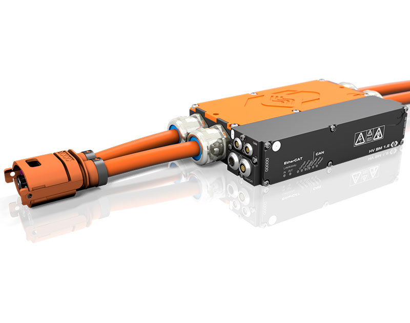
    • Optional plug & play as a ready prepared, HV-safe plug-in system utilizing an HV Cable Adapter from CSM

  • Phoenix terminals (for the HV BM 3.1 only)
    • Cable routing via cable glands
    • Optional plug & play as a ready prepared, HV-safe plug-in system utilizing an HV Cable Adapter from CSM

  • PowerLok connector system with interlock capability (provided with the HV BM "C" variants)
HV BM Typ 3.3 und HV BM Typ 3.3C
HV BM Type 3.3 and HV BM Type 3.3C

Description

Connection of the HV cables with ring terminals

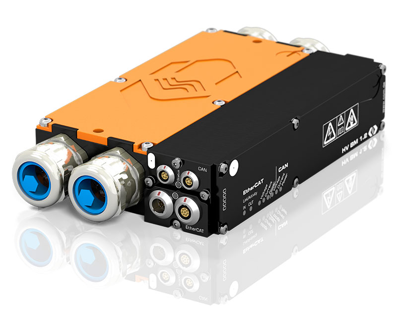
Depending on the diameter of the HV cables, various sized ring terminals are available for connecting the inner conductor ot the measurement points inside the HV BM. Appropriately sized cable glands are attached to the housing of the HV BM. The cable glands ensure a seal around the cable insulation to achieve IP-67 rating

The cable shield is connected to the triangle spring inside the cable gland and makes contact with the HV BM housing. This is done on both sides of the module providing continuity of the shield. Optionally, the braided shield can be routed separately into the HV BM housing and attached to another shunt, e.g. specifically for measuring the shield currents with the HV Breakout Module 1.2+S.

With the cable glands, the HV Breakout Modules can be used safely and even under demanding conditions in test vehicles.

Customer-specific, HV-safe plug-in systems

Optionally, customer-specific, HV-safe plug-in systems can also be individually prepared. The project-specific connector system is attached to the HV cables.

PowerLok Connector System

With the connector systems PL500 (for HV Breakout Module 1.2C) or PL300 (for HV Breakout Module 3.3C), the HV power cables on test benches can be easily and safely connected to, and subsequently disconnect from the HV Breakout Modules. The cable shield is also contacted to the housing via the connector system with this quick connection system.

Both the PL500 and PL300 are interlock-capable and when plugged in, the connector system offers protection in accordance with protection class IP67. Color coding of the sockets on the HV Breakout Module 1.2C facilitates the proper connection of the separate HV+ and HV- power cables.

Appropriate crimping tools are available for attaching the appropriate connectors to the HV cables. This also allows connectors to be attached to the cables directly on site.

Thanks to the robust design of the PowerLok connectors, high mating cycles and the simple connection, measurement setups can be set up easily and DUTs can be replaced quickly. This makes the "C" variants of the HV Breakout Modules particularly suitable for use on test benches.

Technical data

HV Breakout Modules with ring terminals and Phoenix terminals

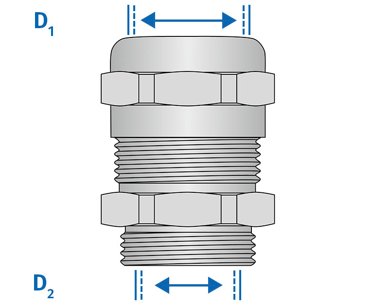
Cable gland type 9/14 11/20 15/25 Cable connection
Cable outer diameter
D1 maximum 14 mm 20 mm 25 mm
D1 minimum 9 mm 11 mm 15 mm
D2 maximum 12 mm 17 mm 21 mm
HV Breakout Modules
HV BM 1.1 3 ring terminals
per side
HV BM 1.2 2 ring terminals
per side
HV BM 1.2+S 3 rings terminal
per side
HV BM 3.3 3 ring terminals
per side
HV BM 3.1 OBC Three special sizes available
See data sheet
3 ring terminals
per side
HV BM 3.1 Phoenix terminals

HV Breakout Modules with PowerLok connector system

HV Breakout Modules Cable connection
HV BM 1.2C PL500 connector
HV BM 3.3C PL300 connector

Click on the corresponding module designation for more information.

Cable gland
Cable gland
HV BM Type 1.2  with HV-safe plug-in system
HV BM Type 1.2 with connected cables, connectors and socket as a ready prepared, HV-safe plug-in system.
HV BM Type 3.3C with PL300 connector