HV Breakout Module 3.1
Three-phase measurement of internal conductor current, voltage and instantaneous power
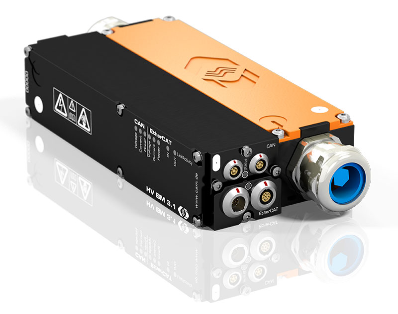
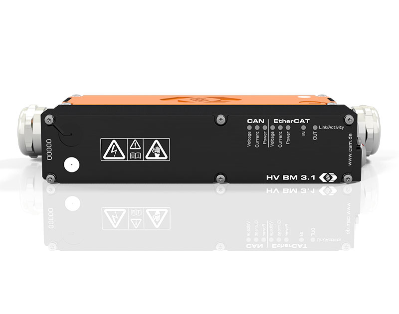
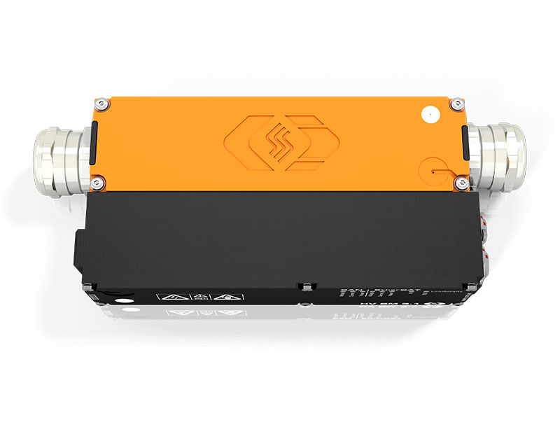
The HV Breakout Module (BM) Type 3.1 is suitable for three-phase current, voltage and power measurement at three-phase charging stations with HV voltage carrying cables with currents up to ±32 A.
Highlights
- Measurement of voltage (U) and internal conductor current (I) in HV applications
- Voltages up to ±1,000 V
- Currents up to ±32 A (rated), ±50 A (peak)
- Calculation of the instantaneous power in the module
- Simultaneous EtherCAT® and CAN bus communication
- Output of voltage, current and instantaneous power with up to 500 kHz measurement data rate
- Online power analysis with the Vector eMobilityAnalyzer
Description
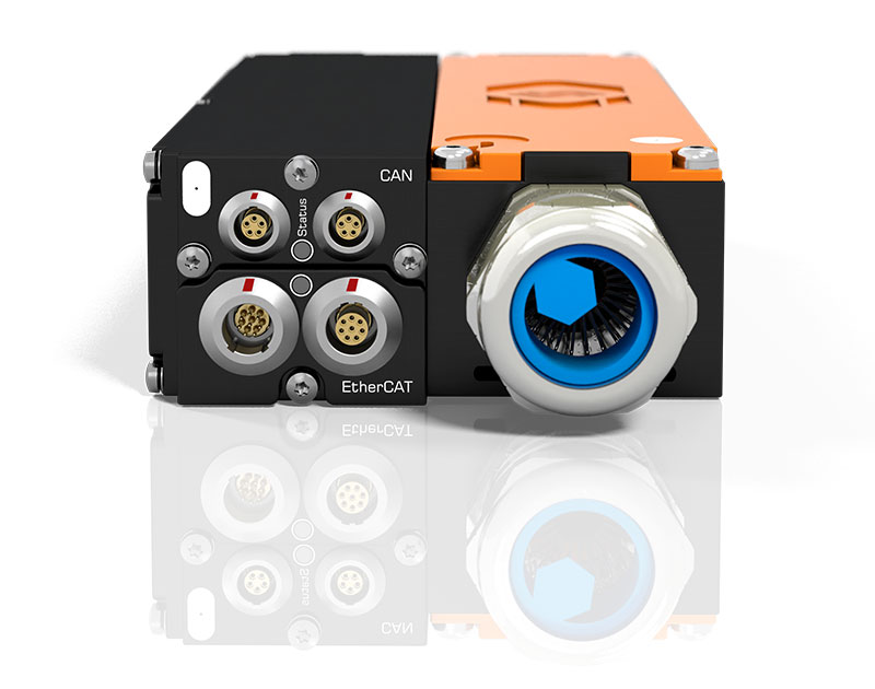
The HV BM is inserted into the typically 5-wire HV cable by feeding the cable through cable glands into the interior of the module and connecting it there using Phoenix terminals. The three-phase measurement with only one measuring device offers enormous cost and space advantages.
The three currents and voltages are measured with reference to the neutral conductor and this measuring circuit (3P4W) is already applied in the module.
The HV BM 3.1 outputs the measurement data with a maximum data rate of up to 500 kHz via the EtherCAT® interface and simultaneously with a data rate of up to 5 kHz via the additional CAN interface. This enables fast data acquisition via Ethernet with simultaneous data recording via CAN.
Technical data
| HV Breakout Module Type 3.1 | ||
|---|---|---|
| Inputs | 5-wire HV power cable to be connected internally via Phoenix terminals Cable cross-section each max. 6 mmm² |
|
| Number of measured phases | 3 | |
| Number of cable glands | 1 per side |
|
| Cable outer diameter | from 11 mm up to 20 mm | |
| Measurement signals | Inner conductor current, voltage and instantaneous power | |
| Inner conductor current | ±32 A rated current Configurable measurement ranges: ±5, ±10, ±25, ±50 A |
|
| Voltage | ±50, ±100, ±200, ±500, ±1,000 V | |
| Instantaneous power | Results from the product of the configured measurement ranges | |
| Power calculation | Permanently online with 500 kHz | |
| Measurement data rate | ||
| ECAT | 1, 2, 5, 10, 20, 50, 100, 200, 500 kHz | |
| CAN | 1, 2, 5, 10, 20, 50, 100, 200, 500 Hz, 1, 2, 5 kHz | |
| Measurement categories | ||
| CAT 0 | 1,000 V | |
| CAT II | 600 V | |
| CAT III | 300 V | |
| Operating conditions | ||
| Housing protection class | IP67 | |
| Operating temperature range | -40°C to +120°C | |
| Pollution degree | 4 | |
Applications
The HV Breakout Module 3.1 is particularly suitable for measurements at HV charging stations and wallboxes as well as between charging station and on-board charger in vehicles.
The measured currents and voltages form the basis for further analyses with the Vector CSM E-Mobility Measurement System.
Further Information
-
CSM Xplained: Testing of fuel cell drives on test benches and in road testing
-
CSM Xplained: Maintenance of HV measurement technology – calibration and insulation-test
-
CSM Xplained: The Vector CSM E-Mobility Measurement System
-
CSM Xplained: Voltage measurement in e-mobility
-
CSM Xplained: Current measurement in e-mobility
-
CSM Xplained: Autonomous power measurement in road tests and on test benches
Downloads
- Configuration software for CSM measurement modules (incl. documentation)
- with visualization software CSMview
- System requirements:

 Home
Home


