Experimental stress analysis of components
How to measure the loads a crane jib can withstand?
Various tests are performed to determine the safety and adequate design of components. In the process, some test parts are stressed to the point of destruction. This approach is particularly important for elements that are subject to high mechanical stress, such as commercial and construction vehicles. Strain gauges are often used to measure the forces acting on the parts. The subsequent analysis of the measured data makes it possible to check if the system meets design intent.
- vMeasure
Data acquisition and evaluation - 48 strain gauges
For the measurement of mechanical stresses - CSM DMS-Sensor-Cables
with internal half-bridge completion close to the sensor - ECAT STG6 BK20 /HE
Synchronous acquisition of sensor data and internal completion to full bridge - XCP-Gateway
Acquires all measurement data and converts them to XCP-on-Ethernet - Special rig
Is lifted by a crane to induce the load - Load cell
Measures the acting force - Measurement setup
Is transported completely and preconfigured from the preparation to the test bench
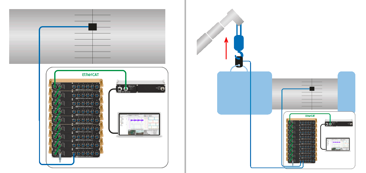
Measurement setup for preparation (left) and testing (right).

Measure loads to verify design
To ensure that components are optimally manufactured, they are thoroughly tested for various types of stress. The aim is to achieve the right balance between material and manufacturing costs while ensuring sufficient safety and durability. A distinction is made between measurements of the loads in real operation or at the limit, and destructive tests. One way to collect data is with experimental stress analysis using strain gauges. In destructive tests, the strain gauges are applied to the relevant points and the components are then loaded until they reach the point of material fatigue. Construction machines and their parts are tested in special test centers to enable accurate statements to be made regarding maximum overload. With the measured stress curves, the calculations of the design department can be verified to determine the ideal material design.
Measurement task
Measurement of mechanical stresses for the verification of simulations.

Many strain gauges required
Efficient execution of the required tests saves time and costs in the testing processes, so a coordinated measurement technology solution can help to simplify the workflows. At the same time, the data from many stain gauges must be acquired synchronously for the precise measurement of the mechanical stresses in the structures of the various jib sections. A data rate of at least 200 Hz per measurement channel is also necessary for the desired accuracy, as well as a high total sampling rate to synchronize the numerous measurement channels. Since short-term peaks are also to be expected, the measurement range needs to be sufficient to capture these spikes.

Thought-out process for quick and accurate results
For the investigation, the jibs of two cranes were each equipped with 48 strain gauges. Some of the strain gauges were applied as single strain gauges, while three strain gauges were glued to the center of the flanks as a rosette to measure stress curves. To compensate for temperature influences, self-compensating strain gauges were selected specifically for the material of the crane jibs and connected to STG6 BK20 modules. The strain gauge sensor cables from CSM offer internal half-bridge completion close to the sensor. The measurement modules allow the internal conversion of the measurement signal directly into strain. Thus, the measurement channel outputs the measured variable as μm/m, since the necessary material- and sensor-specific factors can be easily entered with CSMconfig software and saved in the module. This simplifies the subsequent analysis, since no conversion is necessary after the measurement. At the same time, the data from all 48 strain gauges are acquired synchronously. All STG6 BK20 modules are networked via EtherCAT® and connected to an XCP-Gateway as a protocol converter. The XCP-Gateway acts as an EtherCAT® master for all measurement modules, ensures time synchronization and allows easy connection to Vector's vMeasure data acquisition software.
Transportation and test of the components on the test bench
The test cranes are individually equipped with the strain gauges and measurement modules and then prepared for transport to the test stand. While one jib section is undergoing the test, another one is already being prepared to ensure a seamless process. Before the measurement begins, all measurement channels are zeroed again in CSMconfig. At the test stand, the jib section is mounted on one side and fixed to the floor, while the test object is loaded via the free side. A load cell is used to measure the force applied until the jib breaks. The measurement range of the STG6 BK20 is large enough to capture a wide range of signals. At the same time, the tests are accompanied by high-speed cameras, which also help to visualize the progression of the damage.
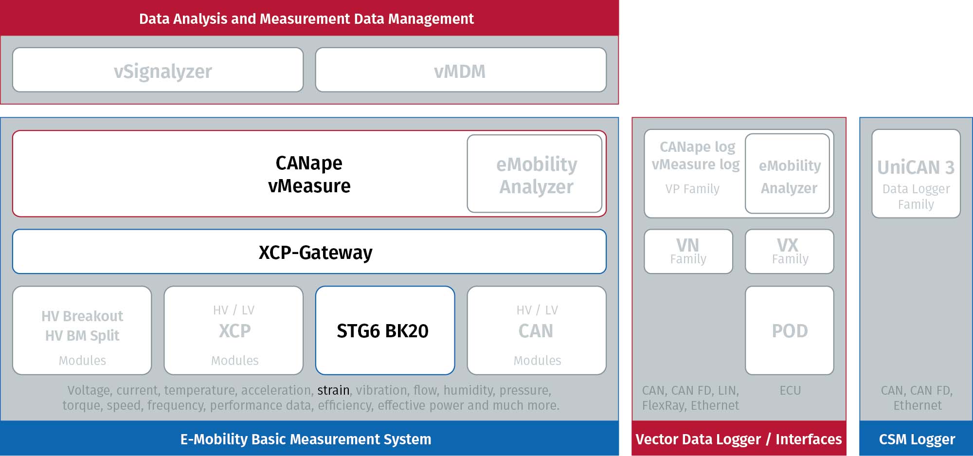

Robust measurement technology
The compact and weatherproof measurement technology makes it possible to work in parallel during preparation and the actual test. It can be easily transported with the test object to the respective locations. The simple cabling and configuration with CSMconfig also ensures efficiency. Due to the data transmission via EtherCAT®, all measurement points can be recorded synchronously. Measurements of mechanical load can be performed quickly and accurately in this way.
Featured Products
Related Hardware

The Vector CSM E-Mobility Measurement System
The measurement system for the development of electric mobility
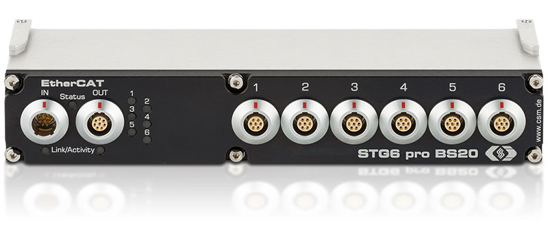
STG6 ECAT MM-Series
Fast distributed strain gauge measurements
Type STG6 pro BS20 | STG6 BK20
EtherCAT®-based measurement modules for decentralized use under demanding conditions: Robust, very compact and with six time-synchronous strain gauge inputs for quarter, half and full bridges.
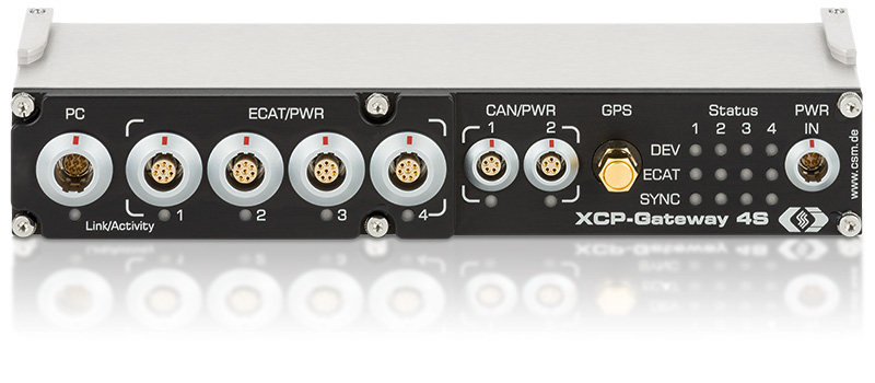
XCP-Gateway
The protocol converter for EtherCAT® and CAN to XCP-on-Ethernet
XCP-Gateway is the interface between the data acquisition software (e. g. vMeasure, CANape®, INCA®, Vision® ...) and the EtherCAT® measurement modules from CSM. It includes an EtherCAT® master and an XCP-on-Ethernet slave.
Related Software
vMeasure
Reliably Solving Complex Measurement Tasks
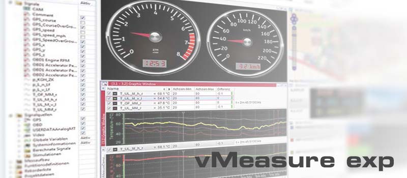
vMeasure, developed by Vector Informatik, is an easy-to-use software tool for the acquisition and analysis of measurement data that can be used in combination with all CAN- and EtherCAT®-based CSM measurement modules. CSMconfig was integrated directly to ensure swift configuration.
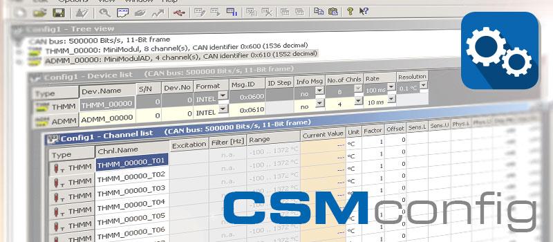

Swift configuration of measurement chains: CSMconfig is the reliable configuration software for all CAN and EtherCAT® based measurement modules from CSM. The clearly arranged and easy-to-use user interface allows an easy setting of all measurement parameters. This helps speeding up the measurement setup considerably.

 Home
Home Newsletter


