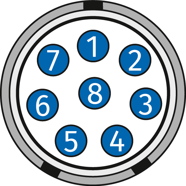
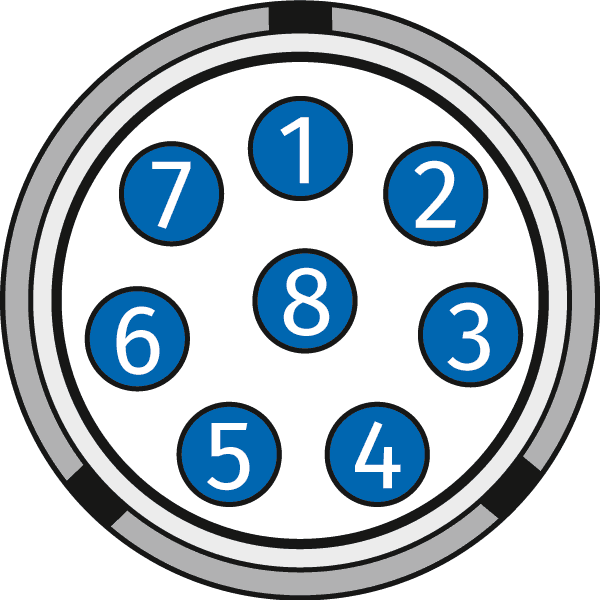
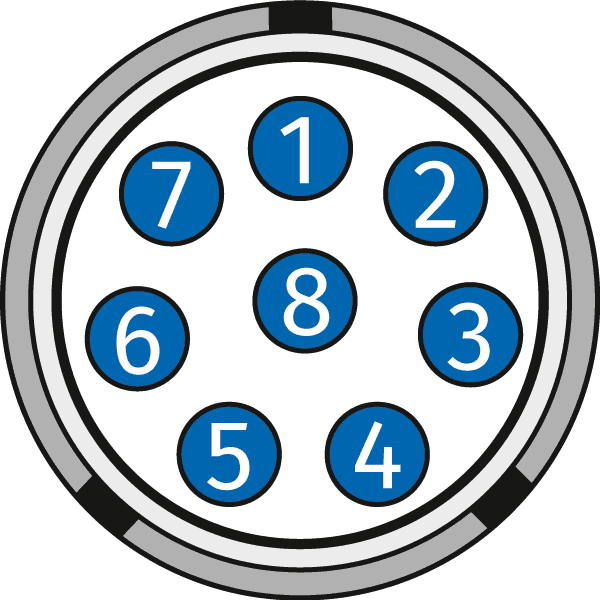
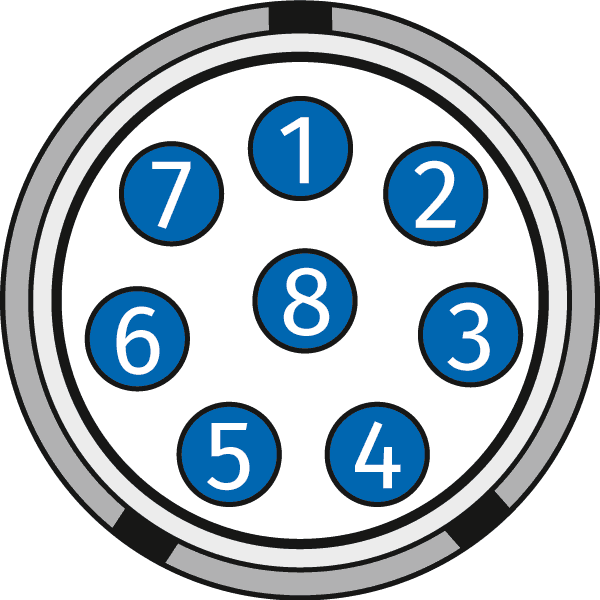
What is the PIN assignment of the signal sockets of the different HV measuring modules?
| Pin | Signal | Description | |
|---|---|---|---|

Code B |
1 | V1IN+ | Channel 1 Input voltage, plus (K1 +) |
| 2 | V1IN- | Channel 1 Input voltage, minus (K1 -) | |
| 3 | V2IN+ | Channel 2 Input voltage, plus (K2 +) | |
| 4 | V2IN- | Channel 2 Input voltage, minus (K2 -) | |
| 5 | V3IN+ | Channel 3 Input voltage, plus (K3 +) | |
| 6 | V3IN- | Channel 3 Input voltage, minus (K3 -) | |
| 7 | V4IN+ | Channel 4 Input voltage, plus (K4 +) | |
| 8 | V4IN- | Channel 4 Input voltage, minus (K4 -) |
*For the HV AD8 OW20 the second signal socket is assigned identically to the first socket.
| Pin | Signal | Description | |
|---|---|---|---|

Code D |
1 | V1IN+ | Channel 1 Input voltage, plus (K1 +) |
| 2 | V1IN- | Channel 1 Input voltage, minus (K1 -) | |
| 3 | V2IN+ | Channel 2 Input voltage, plus (K2 +) | |
| 4 | V2IN- | Channel 2 Input voltage, minus (K2 -) | |
| 5 | V3IN+ | Channel 3 Input voltage, plus (K3 +) | |
| 6 | V3IN- | Channel 3 Input voltage, minus (K3 -) | |
| 7 | V4IN+ | Channel 4 Input voltage, plus (K4 +) | |
| 8 | V4IN- | Channel 4 Input voltage, minus (K4 -) |
| Pin | Signal | Description | |
|---|---|---|---|

Code C |
1 | V1IN+ | Channel 1 Input voltage, plus |
| 2 | V1IN- | Channel 1 Input voltage, minus | |
| 3 | V1OUT+ | Channel 1 Sensor supply output, plus | |
| 4 | V1OUT- | Channel 1 Sensor supply output, minus | |
| 5 | V2IN+ | Channel 2 Input voltage, plus | |
| 6 | V2IN- | Channel 2 Input voltage, minus | |
| 7 | V2OUT+ | Channel 2 Sensor supply output, plus | |
| 8 | V2OUT- | Channel 2 Sensor supply output, minus |
*For the HV AD8 OW20 the further signal socket is assigned identically to the first socket.
| Pin | Signal | Description | |
|---|---|---|---|

Code B |
1 | K1+ | Channel 1 Input voltage, plus |
| 2 | K1- | Channel 1 Input voltage, minus | |
| 3 | K2+ | Channel 2 Input voltage, plus | |
| 4 | K2- | Channel 2 Input voltage, minus | |
| 5 | K3+ | Channel 3 Input voltage, plus | |
| 6 | K3- | Channel 3 Input voltage, minus | |
| 7 | K4+ | Channel 4 Input voltage, plus | |
| 8 | K4- | Channel 4 Input voltage, minus |
*For the HV TH8 and HV TH TBM8, the second signal socket is assigned identically to the first socket.
| Pin | Signal | Description | |
|---|---|---|---|

Code C |
1 | V1IN+ | Channel 1 Input voltage, plus |
| 2 | V1IN- | Channel 1 Input voltage, minus | |
| 3 | I1OUT+ | Channel 1 Sensor supply output (current), plus | |
| 4 | I1OUT- | Channel 1 Sensor supply output (current), minus | |
| 5 | V2IN+ | Channel 2 Input voltage, plus | |
| 6 | V2IN- | Channel 2 Input voltage, minus | |
| 7 | I2OUT+ | Channel 2 Sensor supply output (current), plus | |
| 8 | I2OUT- | Channel 2 Sensor supply output (current), minus |
*For the HV PT TBM8, the other signal sockets are assigned identically to the first socket.
| Pin | Signal | Description | |
|---|---|---|---|

Code E |
1 | VIN+ | Input voltage plus |
| 2 | VIN- | Input voltage minus | |
| 3 | VOUT+ | Bridge excitation voltage plus | |
| 4 | VOUT- | Bridge excitation voltage minus | |
| Channel shield | Shield for measurement signal | ||
| 5 | VSENSE+ | Sense plus | |
| 6 | VSENSE- | Sense minus | |
| 7 | TEDS GND | TEDS Ground | |
| 8 | TEDS Data | TEDS Data line |
*For the HV STG4 pro BS20, the other signal sockets are assigned identically to the first socket.
| Pin | Signal | Description | |
|---|---|---|---|

Code C |
1 | x-axis | Measurement signal for the x-axis |
| 2 | y-axis | Measurement signal for the y- axis | |
| 3 | z-axis | Measurement signal for the z- axis | |
| 4 | GND | Ground of measurement signal | |
| 5 | n.c. | Not connected | |
| 6 | n.c. | Not connected | |
| 7 | n.c. | Not connected | |
| 8 | n.c. | Not connected |

 Home
Home Newsletter


