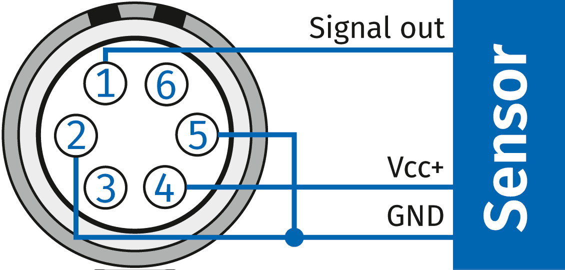
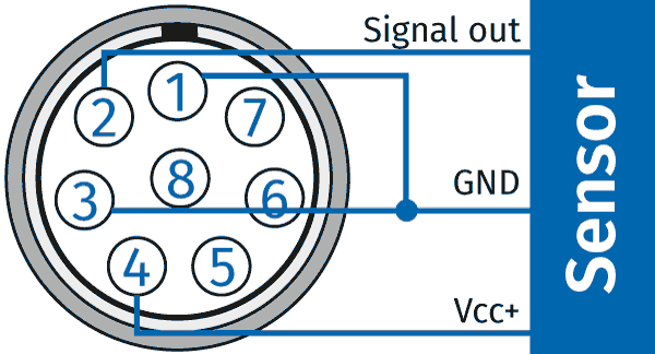
My sensor has three connectors. How do I connect it to my ADMM?
The AD MM series measures the input voltage (=> output voltage of the sensor) using VIN + and VIN - . These PINs are isolated from the rest of the module and have no defined potential unless a sensor is connected.
Since sensors measure the output voltage relative to the sensor ground, VIN- must also be connected to the sensor ground.
| Connector measuring input | Pin | Signal (unipolar sensor supply) |
Signal (bipolar sensor supply) |
Description |
|---|---|---|---|---|

LEMO 0B, 6pol |
1 | VIN + | VIN + | Input voltage, positive |
| 2 | VIN - | VIN - | Input voltage, negative | |
| 3 | -- | -- | Reserved, not connected | |
| 4 | VOUT + | VOUT + | Sensor supply output, positive | |
| 5 | VGND | VGND | Sensor supply ground | |
| 6 | -- | VOUT - | Sensor supply output, negative |
| Connector measuring input | Pin | Signal (unipolar sensor excitation) |
Signal (bipolar sensor excitation) |
Descritption |
|---|---|---|---|---|

LEMO 1B, 8pol |
1 | VIN - | VIN - | Input voltage, negative |
| 2 | VIN + |
VIN + |
Input voltage, positive | |
| 3 | VGND | VGND | Sensor supply ground | |
| 4 | VOUT + | VOUT + | Sensor supply output, positive | |
| 5 | - | VOUT - | Sensor supply output, negative | |
| 6 | - | - | Reserved, not connected | |
| 7 | Channel Shield | Channel Shield | Shield for measurement signal | |
| 8 | Data | Data | Data line (TEDS) | |
| Housing | Cable Shield | Cable Shield | Outer Shield (housing) |

 Home
Home Newsletter


