

HV Breakout Module 1.2+S 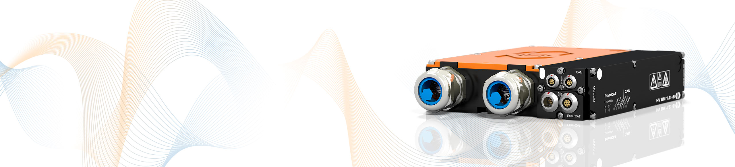
The HV Breakout Module (BM) type 1.2+S is specially designed for single-phase measurements on HV voltage power cables. It is suitable to simultaneously measure power, inner conductor current, shield current and voltage.

The HV BM 1.2+S is inserted directly into the HV power cables (HV+/HV-) by passing the cables through cable glands into the interior of the module and connecting them there using ring terminals.
The voltage is measured directly. The current measurements are performed via two shunt modules, which contain differential amplifiers as well as temperature sensor and memory for calibration data for automatic online temperature compensation. One shunt is used for the inner conductor current, the other for the shield current.
The HV BM 1.2+S outputs the measurement data with a maximum data rate of up to 1 MHz via the EtherCAT® interface and simultaneously with a data rate of up to 10 kHz via the additional CAN interface. This enables fast data acquisition via Ethernet with simultaneous data recording via CAN.
With the option Calc. active, apparent and reactive power, power factor as well as the RMS values for current (inner conductor current) and voltage can be calculated directly in the module from the sampled measured values. Via CAN the calculated values are directly transmitted to the measurement computer or a data logger.
| HV Breakout Module Type 1.2+S | ||
|---|---|---|
| Inputs | HV power cable for HV+ and HV- | |
| Number of measured phases | 1 | |
| Number of cable glands | 2 per side | |
| Cable outer diameter | 9 mm to 25 mm Depending on the mounted cable glands. See datasheet. | |
| Measurement signals | Shield current, inner conductor current, voltage and instantaneous power | |
| Shield current (Rated current) | ±50 up to ±250 A Four configurable measuring ranges, depending on the mounted shunt module. See datasheet. | |
| Inner conductor current (Rated current) | ±50 up to ±1,000 A Four configurable measuring ranges, depending on the mounted shunt module. See datasheet. | |
| Voltage | ±100, ±200, ±500, ±1,000, ±2,000 V For the acquisition of transient overvoltage, the measuring range is dimensioned to ±2,000 V. | |
| Power calculation | Permanently online with 1 MHz | |
| Measurement data rate | ||
| ECAT | 1, 2, 5, 10, 20, 50, 100, 200, 500, 1,000 kHz | |
| CAN | 1, 2, 5, 10, 20, 50, 100, 200, 500 Hz, 1, 2, 5, 10 kHz | |
| Output signals | ||
| ECAT | Voltage, shield current, inner conductor current, instantaneous power | |
| CAN | Voltage, shield current, inner conductor current With option Calc. additionally: RMS values for voltage and current (inner conductor current), active power, apparent power, reactive power and power factor Lambda | |
| Integration time RMS value and power calculation | 10 ms to 10 s | |
| Operating conditions | ||
| Housing protection class | IP67 | |
| Operating temperature range | -40°C to +120°C | |
| Pollution degree | 4 | |


With the HV Breakout Module 1.2+S, shield currents can be measured safely and precisely at many points in the vehicle electrical system. In addition to the measurement of shield currents, the internal conductor current and HV voltage are also acquired - the synchronous measurement of all measured variables in a single module considerably simplifies handling and instrumentation. The high-voltage vehicle electrical system can be designed safely and efficiently on the basis of the subsequent analyses, and serious consequences such as cable fires and premature component failures can be avoided.
The direct output of power and RMS values allows various analyses without the use of special hardware and software in the road test. More in-depth analyses, such as the investigation of leakage currents and symmetries as well as the correlation with measured values from further CSM measurement modules (e.g. temperatures) can be performed with the Vector CSM E-Mobility Measurement System.