

HV Split Breakout Module Voltage 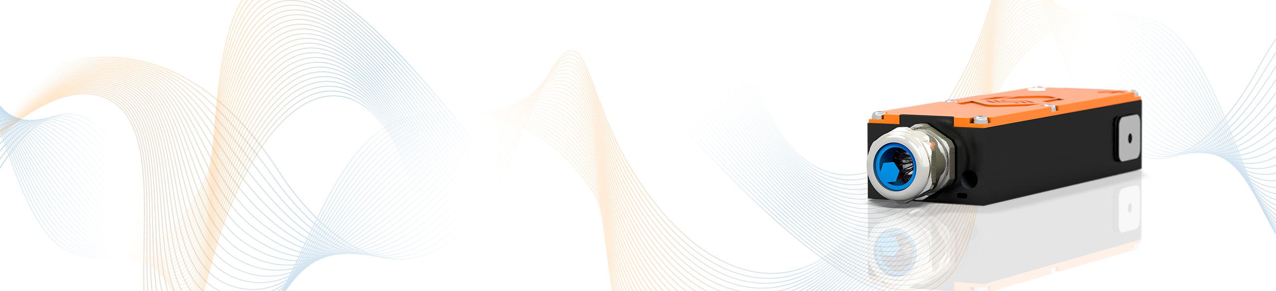
The HV split Breakout Modules (HV SBM_U) allow safe voltage tapping (HV+) in HV power cables that run between closely installed components or in cable ducts. The encapsulated housing protects the voltage tap from environmental influences and ensures HV safety for users and components. The voltage is measured in the HV SAM (HV Split Acquisition Module).

The HV Split Breakout Modules U tap the HV+ potential in the HV cables. The voltage measurement is carried out in combination with a HV SBM_I (HV- potential tap) in the HV SAM (HV Split Acquisition Module).
The HV cables are fed into the housing through cable glands and connected inside via ring terminals. The cable shield is placed on the housing or passed through.
The HV SBM_U is connected to the HV SAM measurement module via a plug-in connection using an HV-safe and shielded sensor cable that is permanently installed in the HV SBM_U.
| HV SBM_U | |
|---|---|
| Inputs | HV+ power cable |
| Nuber of measured phases | 1 |
| Connection of HV+ power cable | Ring terminals (via cable glands) |
| Number of cable glands | 1 on each side |
| Outer cable diameter | 9 mm to 25 mm See data sheet |
| Measurement signal | Potential (HV+) |
| Measurement categories | |
| CAT 0 | 1,000 V |
| CAT II | 600 V |
| CAT III | 300 V |
| Operating conditions | |
| Housing protection class | IP67 |
| Operating temperature range | -40°C to +120°C |
| Pollution degree | 4 |
| Safety conformity | EN 61010-1:2020 |


The HV Split Breakout Modules tap the HV+ voltage potential in HV power cables that run between tightly installed components or in cable ducts and where no space is available for the installation of conventional HV Breakout Modules. The encapsulated housing of the HV SBM_U allows easy and safe application.
With the measurement data obtained from the HV BM Split Modules and the eMobilityAnalyzer from the Vector CSM E-Mobility Measurement System a variety of analyses in real time can be performed: Inverter and powertrain efficiency calculations, e-motor power analysis, harmonic analysis, PWM analysis, ripple analysis and many more.
