

HV Split Acquisition Module 1.1 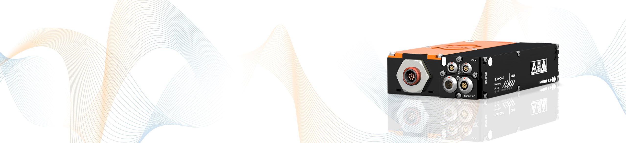
The HV Split Acquisition Module 1.1 (HV SAM 1.1) acquires the current and voltage values of HV Split Breakout Modules and also performs filtering, online calculation of RMS values and powers, and data output via EtherCAT® and CAN.

By separating the sensor modules (HV SBM) and the HV SAM measurement module, the elements can be arranged spatially separately. While the sensor modules integrate almost perfectly into the HV cable routing due to their design, the measurement module does not have to be integrated directly into the measurement point.
The HV SBMs are connected to the measurement module via a HV-safe and shielded sensor cable. The sensor cable is also used to supply the measuring electronics in the shunt module of the HV SBM_I. As an alternative for the HV SBM_U, a HV-safe sensor cable for the voltage tap (HV+) can also be connected.
The HV SAM 1.1 measurement module provides the data acquisition, filtering and online calculation of RMS values and power. In addition, the encapsulated housing and the galvanic isolation between HV SBM and SAM ensure HV safety for users and components.
Currents are measured directly in the corresponding HV Split Breakout Modules (HV SBM_I, HV SBM_I open, HV SBM_I/U). Voltage measurement is performed in the HV SAM 1.1 based on the measured HV+ and HV- potentials (tap HV+ via HV SBM_U, HV SBM_I/U or sensor cable).
The measurement data is passed on via EtherCAT® and CAN bus.
With the option Calc. active, apparent and reactive power, power factor as well as the RMS values for current and voltage can be calculated directly in the module from the sampled measured values. Via CAN the calculated values are directly transmitted to the measurement computer or a data logger.
| HV SAM 1.1 | ||
|---|---|---|
| Inputs | 2 analog inputs (voltage, current) | |
| Number of measured phases | 1 | |
| Measurements signals | Inner conductor current and voltage | |
| Inner conductor current (Nominal) | ±10 to ±1,000 A Four configurable measurement ranges, depending on shunt module used. See data sheet. | |
| Voltage | ±100, ±200, ±500, ±1,000, ±2,000 V For the acquisition of transient overvoltage, the measuring range is dimensioned to ±2,000 V. | |
| Measurement data rate | ||
| ECAT | 1, 2, 5, 10, 20, 50, 100, 200, 500, 1,000 kHz | |
| CAN | 1, 2, 5, 10, 20, 50, 100, 200, 500 Hz, 1, 2, 5, 10 kHz | |
| Output signals | ||
| ECAT | Voltage, current, instantaneous power | |
| CAN | Voltage, current With option Calc. additionally: RMS values for voltage and current, active power, apparent power, reactive power and power factor Lambda | |
| Integration time RMS value and power calculation | 10 ms to 10 s | |
| Measurement categories | ||
| CAT 0 | 1,000 V | |
| CAT II | 600 V | |
| CAT III | 300 V | |
| Operating conditions | ||
| Housing protection class | IP67 | |
| Operating temperature range | -40°C bis +120°C | |
| Pollution degree | 4 | |
| Safety conformity | EN 61010-1:2020 | |


Due to the separate design of sensor modules and measuring modules, the HV BM Split modules can be flexibly integrated into the measuring points.
The direct output of power and RMS values allows various analyses without the use of special hardware and software in the road test. More in-depth analyses, such as the investigation of leakage currents and symmetries as well as the correlation with measured values from further CSM measurement modules (e.g. temperatures) can be performed with the Vector CSM E-Mobility Measurement System.
