

HV Breakout Module 1.2+U 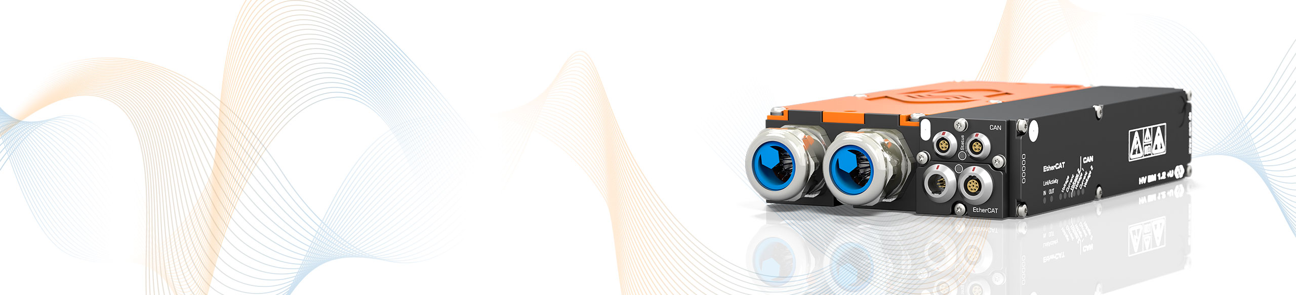
The HV Breakout Module (BM) type 1.2+U is specially designed for single-phase measurements on HV voltage power cables. HV BM 1.2 are suited for simultaneous measurement of internal conductor current and voltage. With HV BM 1.2+U in addition the voltages of HV+ to ground (PA) and HV- to ground are measured.

The HV BM 1.2+U is installed into the HV cables by feeding the cables through cable glands into the interior of the module and connecting them with ring terminals.
The measurement of three voltages (HV+ → HV-; HV+ → ground; HV- → ground) and current with just one measurement module offers enormous advantages in terms of space requirements and time needed for instrumentation. The necessary measurements can be carried out with just one module instead of several measurement devices that would have to be used otherwise to get all data.
The three voltages are measured directly by the HV BM 1.2+U. The current measurement is performed with an integrated shunt module, which includes a temperature sensor and a memory chip for the calibration data for automatic online temperature compensation.
The HV BM 1.2+U outputs the measurement data at a maximum data rate of up to 1 MHz per channel via the EtherCAT® interface and simultaneously at a data rate of up to 10 kHz per channel via the additional CAN interface. This enables fast data acquisition via Ethernet and simultaneous data recording with a data logger via CAN.
With the option Calc. active, apparent and reactive power, power factor as well as the RMS values for current and voltage can be calculated directly in the module from the sampled measured values. The calculated values are directly transmitted via CAN to the measurement computer or data logger.
| HV Breakout Module Type 1.2+U | ||
|---|---|---|
| Inputs | Separate HV power cables for HV+ and HV- | |
| Number of measured phases | 1 | |
| Number of cable glands | 2 per side | |
| Cable outer diameter | 9 mm to 25 mm Select suitable cable glands. See datasheet. | |
| Measurement signals | Voltages HV+ → HV-; HV+ → PA; HV- → PA and current | |
| Inner conductor current (Rated current) | ±50 up to ±1,000 A Four configurable measurement ranges, depending on the mounted shunt module. See datasheet. | |
| Voltage | ±100, ±200, ±500, ±1,000, ±2,000 V For the acquisition of transient overvoltage, the measurement range is dimensioned to ±2,000 V. | |
| Measurement data rate | ||
| ECAT | 1, 2, 5, 10, 20, 50, 100, 200, 500, 1,000 kHz | |
| CAN | 1, 2, 5, 10, 20, 50, 100, 200, 500 Hz, 1, 2, 5, 10 kHz | |
| Output signals | ||
| ECAT and CAN | Voltages HV+ → HV-; HV+ → PA; HV- → PA; current, shunt temperature, module temperature | |
| CAN | With option Calc. additionally: RMS values for voltage and current, active power, apparent power, reactive power and power factor | |
| Integration time RMS value and power calculation | 10 ms to 10 s | |
| Measurement categories | ||
| CAT 0 | 1.000 V | |
| CAT II | 600 V | |
| CAT III | 300 V | |
| Operating conditions | ||
| Housing protection class | IP67 | |
| Operating temperature range | -40 °C to +120 °C | |
| Pollution degree | 4 | |


Typical applications are measurements between HV battery and inverter, both to check the symmetry of the supply voltage to PA and to simultaneously characterize a DC consumer and record its interaction with the vehicle electrical system.
The direct output of power and RMS values allows various analyses without the use of special hardware and software in the road test. More in-depth analyses, such as the investigation of leakage currents and symmetries as well as the correlation with measured values from further CSM measurement modules (e.g. temperatures) can be performed with the Vector CSM E-Mobility Measurement System.