Use Cases 
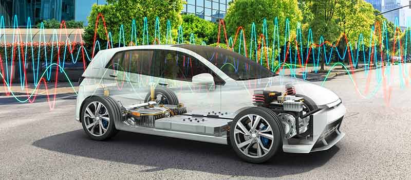
Optimization of electric and hybrid vehicles often focuses on components in the electric powertrain. However, to increase range and efficiency, a perfect balance of weight and stability is required for numerous components. This compromise is particularly challenging for heavily stressed components such as the chassis. This application example shows how the measurements for durability analyses are carried out on tie rods and axle control arms.


As part of the so-called unsprung masses, tie rods and axle control arms have a significant influence on ride comfort and driving dynamics. In order not to endanger safety on the one hand and to allow a comfortable driving experience on the other, a good balance of strength and mass of the components must be achieved.
Simulation models are used during development to simulate the expected forces. To validate the simulations, the forces acting on the axle geometry are measured on the test bench and in road tests and correlated with other values. The forces acting on the control arms and tie rods must be determined in order to measure the fatigue strength. In addition, spring travel, steering angle and speed are to be measured.
Measurement Task
Measurement of forces on control arms and tie rods as well as measurement of spring travel, steering angle and speed.

The acquisition of the required measured values should be carried out in parallel with a single measurement system to allow simple application. In addition, the measurement system should be able to be used in all test scenarios (test bench, road, test track) to avoid long conversion times.
Tie rods and control arms are designed as very stable components, which means that only low strain values are expected in normal driving situations. The measurement technology used must be correspondingly high-resolution in order to be able to precisely acquire even very small signal values.
At the same time, the measurement technology should offer high dynamics in order to be able to measure very high values, such as those that occur during misuse tests.

Components from the Vector CSM E-Mobility Measurement System are used for the measurements. This allows easy acquisition of all measured values with one harmonized measurement system.


With this measurement setup, all required measured variables can be acquired easily and in parallel. The robust and compact design of the measurement modules allows them to be installed close to the measurement point, requires only very short analog signal cables and enables them to be used in road tests and on the test bench.

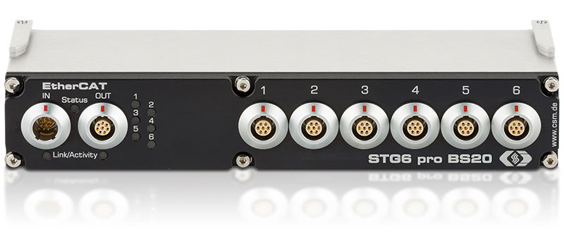
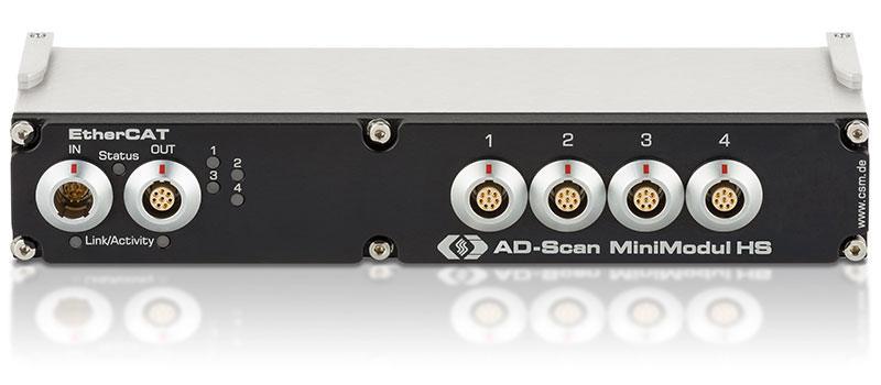
Type STG6 pro BS20 | STG6 BK20
EtherCAT®-based measurement modules for decentralized use under demanding conditions: Robust, very compact and with six time-synchronous strain gauge inputs for quarter, half and full bridges.
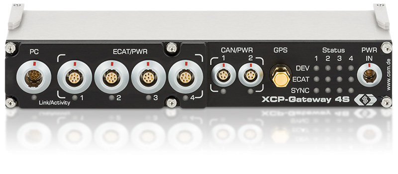
XCP-Gateway is the interface between the data acquisition software (e. g. vMeasure, CANape®, INCA®, Vision® ...) and the EtherCAT® measurement modules from CSM. It includes an EtherCAT® master and an XCP-on-Ethernet slave.
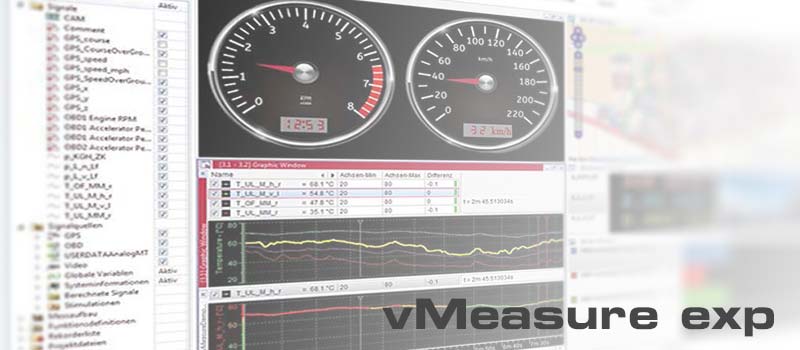
vMeasure, developed by Vector Informatik, is an easy-to-use software tool for the acquisition and analysis of measurement data that can be used in combination with all CAN- and EtherCAT®-based CSM measurement modules. CSMconfig was integrated directly to ensure swift configuration.
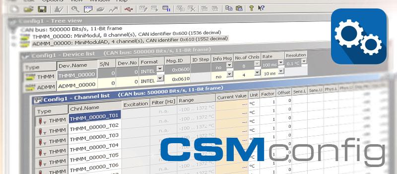

Swift configuration of measurement chains: CSMconfig is the reliable configuration software for all CAN and EtherCAT® based measurement modules from CSM. The clearly arranged and easy-to-use user interface allows an easy setting of all measurement parameters. This helps speeding up the measurement setup considerably.