

Use Cases 
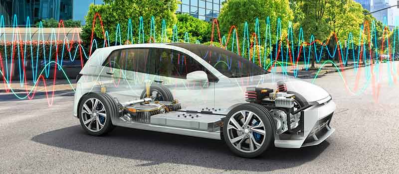
Electric vehicles have two, three or even four electric motors in their powertrain. The interaction of the inverters and electric motors is tested in the early development phase in order to fine-tune the motor control. For this purpose, extensive performance analyses are carried out on the test bench and in the test vehicle. This example shows how an easy scalable measurement setup can be used to perform the necessary performance analyses in real time.

In powertrains with several electric motors, the fine-tuning of power electronics and motors poses a challenge to achieving optimum performance. For the design, extensive measurements are necessary to determine the characteristic and performance values. The performance analyses can be used to verify whether the motor management system executes the control of the electric motors as expected in the various driving situations, e.g. during the rapid changes of acceleration, braking and regeneration.
Furthermore, energy measurements and the analysis of efficiency maps validate the development and range targets.
Measurement Task
Synchronous acquisition of physical values (current, voltage, torque, speed, temperatures) and ECU data for real-time performance analysis.

The measurement system for measuring and analyzing the desired performance parameters must be easily scalable in order to be quickly adapted to the specifics of the power train. All physical variables and the data from control units must be recorded in one system in order to be able to perform accurate analyses with synchronous measured values.
The analyses must be calculated in real time in order to be able to detect direct error reactions. The raw data should also be recorded for precise analysis afterwards. In this way, any problems that occur can be investigated in greater depth at a later date.
The instrumentation should be usable on the test bench and later in the test vehicle. In this way, the results of the test bench analyses can be directly compared with real driving data.


With measurement modules and other components from the Vector CSM E-Mobility Measurement System, the numerous measurement variables required can be acquired and the parameters precisely analyzed.


The decentralized design of the E-Mobility Measurement System makes it easy to instrument test benches and test vehicles with measurement technology. Instrumentation and measurements in component and powertrain test benches are identical to those in test vehicles on vehicle and chassis dynamometers.
A multi-channel power analysis is easy and time-saving to install in powertrains even with several electric motors, for example in all-wheel drive or utility vehicles. If, for example, a four-motor all-wheel drive is to be analyzed, the measurement configuration can be doubled. The power analysis can then be performed on 4 engines and 4 inverters simultaneously. This means that even the most complex powertrains can be measured.
Electrical power measurement is performed via HV Breakout Modules and CANape or vMeasure. Power analyzers and measurement racks are not necessary. Complex, interference-prone cabling between current sensors and power analyzers is eliminated. The installation time of the measurement system is significantly reduced. Sources of error in the cabling of the measurement circuit are eliminated.

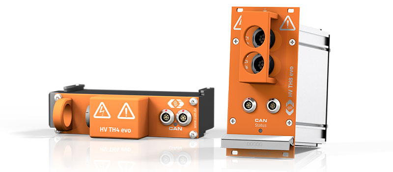
Safe temperature measurements with thermocouples on high-voltage components: the high-voltage-safe temperature measurement modules are specifically designed for the reliable acquisition of temperatures in electric and hybrid vehicles.
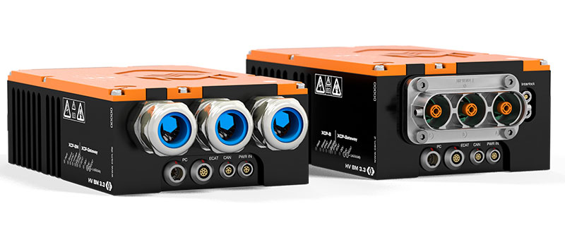
The HV Breakout Modules (BM) Type 3.3 have been specially designed for safe and precise three-phase measurement in HV power cables. The inner conductor currents and outer conductor voltages are directly acquired and output via XCP-on-Ethernet.
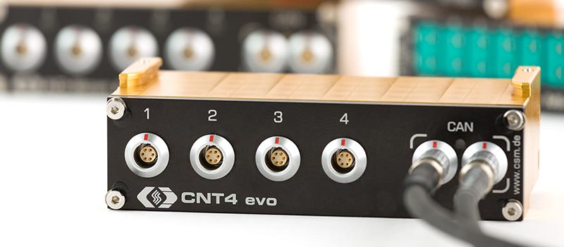
The CNT evo is a high-precision measurement module designed for measuring frequencies, pulse widths, incremental displacement measurements, rotation angles, position measurement, event counting and period measurements.
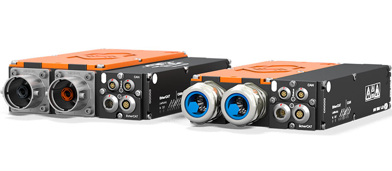
The HV Breakout Modules (BM) Type 1.2 have been specially designed for safe and precise single-phase measurement in separated HV+ and HV- power cables. Inner conductor current and voltage are measured directly and the instantaneous power is calculated in the module.
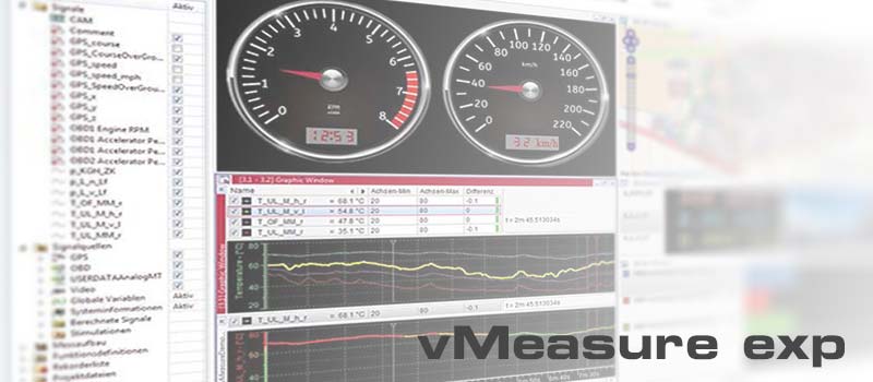
vMeasure, developed by Vector Informatik, is an easy-to-use software tool for the acquisition and analysis of measurement data that can be used in combination with all CAN- and EtherCAT®-based CSM measurement modules. CSMconfig was integrated directly to ensure swift configuration.
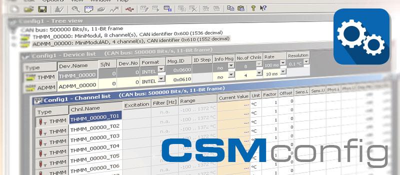

Swift configuration of measurement chains: CSMconfig is the reliable configuration software for all CAN and EtherCAT® based measurement modules from CSM. The clearly arranged and easy-to-use user interface allows an easy setting of all measurement parameters. This helps speeding up the measurement setup considerably.